








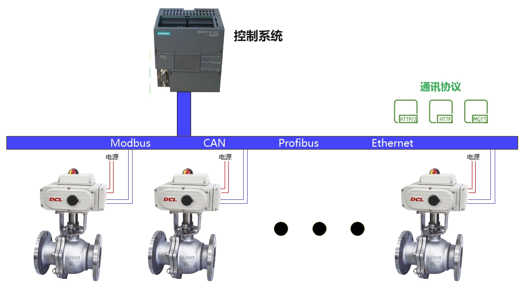
The DCL series actuators support the Modbus-RTU protocol. By referring to this application manual, you can connect the DCL actuator to Modbus.
Panel Description
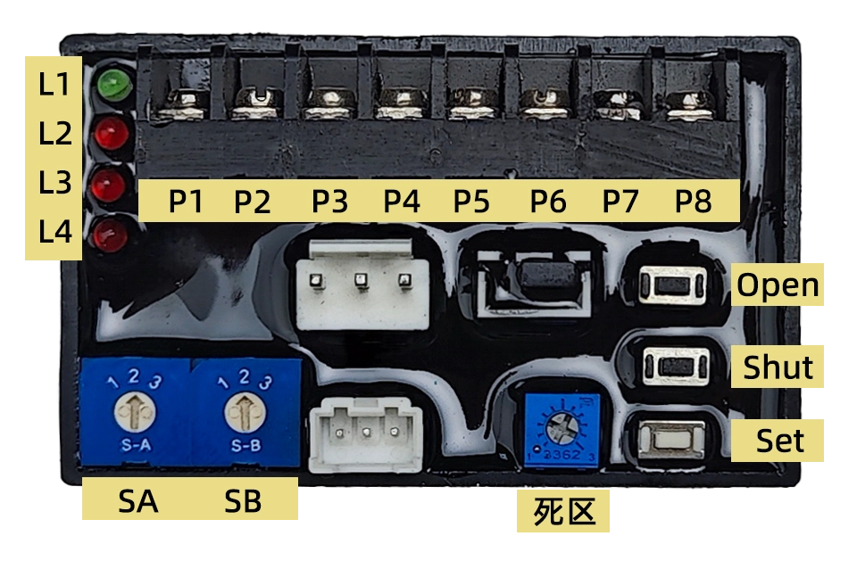
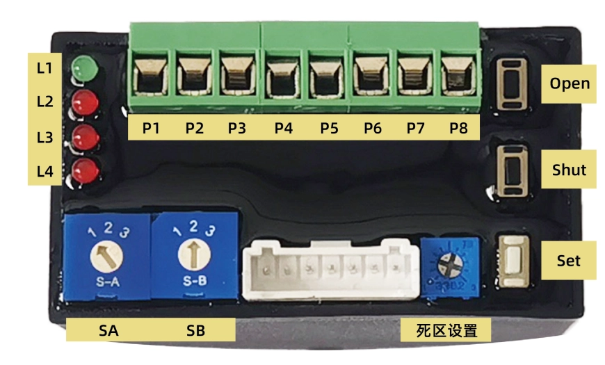
1. インターフェース定義
P1: 220VAC Neutral (N)
P2: 220VAC Live (L)
P3: 4-20mA Input –
P4: 4-20mA Input +
P5: 4-20mA Output –
P6: 4-20mA Output +
P7: RS485 A
P8: RS485 B
2. Buttons
オープンだ: In “Setup Mode” (when switch SA points to “2”), pressing this key opens the actuator, and releasing it stops the motor. Pressing セット そして オープン simultaneously is used for full-open position calibration.
シャットだ: In “Setup Mode,” pressing this key closes the actuator, and releasing it stops the motor. Pressing セット そして シャット simultaneously is used for full-close position calibration.
セット: Used in combination with オープン そして シャット in “Setup Mode” to perform specific functions.
3. Selector Switch
SA: Selects the input signal’s direct/reverse action mode and setup state. It must be set while powered on for it to be effective. Factory default is 1:
1 – Direct Action
2 – Setup Mode
3 – Reverse Action
SB: Sets the safety position. When an external control signal is lost, the actuator moves to the specified position. Factory default is 2:
1 – Move to Full Open
2 – Hold Current Position
3 – Move to Full Close
注: When using Modbus control, SB must be set to position 2.
4. Deadband Value Adjustment Potentiometer
Adjusts the deadband value. Turning clockwise increases the deadband; counterclockwise decreases it. The range is 0.5% – 5.0% (factory default is 1.5%).
5. Indicator Lights
L1(緑): Power Indicator – Lights up when power is supplied.
L2(赤): Input Signal Failure Indicator – Lights up when input signal fails.
L3(レッド): Position Detection Failure Indicator – Lights up if the position potentiometer is open, shorted, or damaged.
L4(レッド): Jamming Failure Indicator – Lights up when jamming occurs.
設定
To enter “Setup Mode,” set SA 位置 2. This mode allows for:
旅行時のキャリブレーション
Input signal failure handling
Deadband value adjustment
Manual operation
出力電流校正
1. Setting End-position
Setting End-position of Close: Adjust the valve to the end-position of close using オープン and/or シャット buttons. Press セット, then シャット, and hold both for about 4秒 まで L2 lights up, then release both buttons. L2 turns off, indicating setting completion.
Setting End-position of Open: Adjust the valve to the end-position of open using オープン and/or シャット buttons. Press セット, then オープン, and hold both for about 4秒 まで L2 lights up, then release both buttons. L2 turns off, indicating setting completion.
2. Setting Modbus Address
The Modbus communication address and baud rate can be modified via Modbus commands.
Factory default address: 1
Factory default baud rate: 9600
3. Deadband Value Adjustment
Turning the potentiometer 時計回り increases the deadband.
Turning it 反時計回り decreases the deadband.
Each tick mark corresponds to a 0.5% change.
If set below 0.5%, it is automatically processed as 0.5%.
で Setup Mode, use オープン または シャット to manually open or close the valve.
Operation
To start automatic operation, set SA 位置 1 または 3.
Upon power-up, the actuator defaults to 4-20mA signal control.
Sending a Modbus command switches the actuator to communication control mode.
After power cycling, the actuator returns to analog control mode.
Important: When using Modbus control:
Ensure SB is set to position 2.
Every control command must include the control mode and position value to prevent unintended actions after a restart.
Using 4-20mA for Position Control
| 入力信号 | 4mA | 8mA | 12mA | 16mA | 20mA |
|---|---|---|---|---|---|
| Pointer Position | CLOSE (0) | 2.5 | 5 | 7.5 | OPEN (100) |
| Valve Opening (%) | 0% | 25% | 50% | 75% | 100% |
| 出力信号 | 4mA | 8mA | 12mA | 16mA | 20mA |
注:
で reverse action mode, 4mA corresponds to 100% openそして 20mA corresponds to 0% open.
Servo controller accuracy level: ±1%
Hysteresis: <1%
Using Modbus to Control Actuator Position
Physical Layer
The DCL actuator supports the Modbus-RTU protocol and uses the RS485 interface at the physical layer.
Communication Address: Configurable from 1 to 127, default is 1.
Baud Rate: Configurable, default is 115200.
Serial Port Format: 1 start bit + 8 data bits + 1 stop bit.
Broadcast Functionality: Supported.
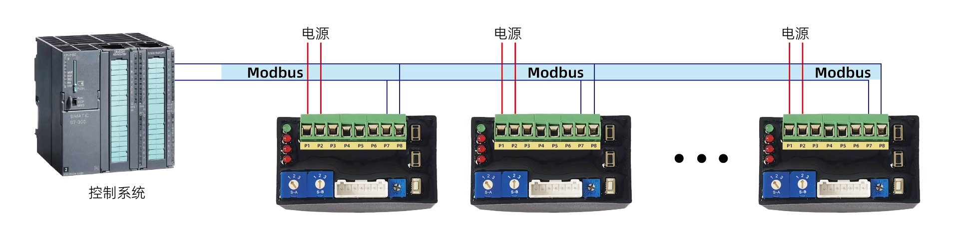
Interface Definition
| Pin | 機能 |
|---|---|
| P1 | Power (-) |
| P2 | Power (+) |
| P7 | RS485 A |
| P8 | RS485 B |
| P3~P6 | Reserved for analog signals (4 |
Modbus Wiring Diagram
アプリケーション層
1. ADU (Application Data Unit)

2. 機能コード
| ID | 名称 | 説明 |
|---|---|---|
| 0x03 | Read Multiple Registers | Reads a block of holding registers from a remote device. |
| 0x06 | Write Single Register | Writes a single register on a remote device. |
| 0x10 | Write Multiple Registers | Writes a block of consecutive registers (1 to approximately 120 registers). |
3. Configuring Communication Parameters
Registers 0x0040 – 0x0042 are used for communication settings:
Write 0xA501 to register 0x0040 を入力する configuration mode.
Modify register 0x0041 (communication address) and register 0x0042 (baud rate).
The new parameters take effect within 1 second, and further communication must use the updated settings.
Exit configuration mode by writing 0x0000 への register 0x0040.
4. Forcing Default Communication Mode
セット SA への ポジション2 そして SB への ポジション2.
を押し続ける。 KS button for about 3 seconds まで。 red light blinks, then release the button.
を押し続ける。 KC button for about 3 seconds まで。 red light stays on, then release the button.
The communication parameters are now reset to default values.
セット SA back to position 1 to exit this mode.
The new settings remain even after restarting the device.
注:
If you forget the previous communication parameters, use this method to restore the default communication mode and configure the communication settings again.
Register List
| Register Address | Bits | Group | Signal Name | Min Value | Max Value | ユニット | R/W | タイプ | 説明 |
|---|---|---|---|---|---|---|---|---|---|
| 0x0010 | b15-b5 | – | – | – | – | – | 読み書き | 16進数 | Reserved (0) |
| b4 | コントロール | 停止 | – | – | – | – | 読み書き | 16進数 | 1: Stop, 0: Normal operation |
| b1-b0 | コントロール | Mode | – | – | – | – | 読み書き | 16進数 | 1: Communication control, others: Exit communication control |
| 0x0011 | b15-b0 | コントロール | オープン学位を設定する | 0 | 10000 | % | 読み書き | 整数/16進数 | 0-10000 corresponds to 0-100% valve opening (scaling factor: 1/100) |
| 0x0018 | b15-b6 | – | – | – | – | – | r | 16進数 | Reserved (0) |
| b5 | info | エラー位置 | – | – | – | – | r | 16進数 | 1: Position signal failure |
| b4 | info | エラーシグナル | – | – | – | – | r | 16進数 | 1: Input signal failure |
| b3 | info | オーバートルクフラグ | – | – | – | – | r | 16進数 | 1: Overload detected |
| b2 | info | スタックフラグ | – | – | – | – | r | 16進数 | 1: Jamming detected |
| b1 | info | openRunフラグ | – | – | – | – | r | 16進数 | 1: Opening valve |
| b0 | info | closeRunFlag | – | – | – | – | r | 16進数 | 1: Closing valve |
| 0x0019 | b15-b0 | info | オープン学位 | 0 | 10000 | % | r | 整数/16進数 | 0-10000 corresponds to 0-100% valve opening (scaling factor: 1/100) |
| 0x0040 | b15-b0 | 設定 | cfgMode | 1 | 127 | – | rw | 16進数 | 0x0000: Normal mode, 0xA501: Configuration mode |
| 0x0041 | b15-b0 | 設定 | cmm_addr | 1 | 127 | – | rw | 16進数 | Sets communication address |
| 0x0042 | b15-b0 | 設定 | cmm_baudrate | – | – | – | rw | 16進数 | 0: 4800 baud, 1: 9600 baud, 2: 19200 baud, 3: 115200 baud |
Communication Command Examples
1. Control Valve Position
Entering Communication Control Mode:
Send → ◇01 10 00 10 00 01 02 00 01 65 00
Receive ← ◆01 10 00 10 00 01 00 0C
Setting Valve Position: 0%
Send → ◇01 10 00 11 00 01 02 00 00 A5 11
Receive ← ◆01 10 00 11 00 01 51 CC
Setting Valve Position: 50% (5000 → 0x1388)
Send → ◇01 10 00 11 00 01 02 13 88 A8 47
Receive ← ◆01 10 00 11 00 01 51 CC
Setting Valve Position: 100% (10000 → 0x2710)
Send → ◇01 10 00 11 00 01 02 27 10 BF 2D
Receive ← ◆01 10 00 11 00 01 51 CC
Stopping Operation
Send → ◇01 10 00 10 00 01 02 00 11 64 CC
Receive ← ◆01 10 00 10 00 01 00 0C
2. Read Valve Status
Send → ◇01 03 00 18 00 02 44 0C
Receive ← ◆01 03 04 00 30 00 00 FA 3C
3. Set Communication Address
Entering Configuration Mode:
Send → ◇01 10 00 40 00 01 02 A5 01 12 00
Receive ← ◆01 10 00 40 00 01 00 1D
Change Communication Address to: 2
Send → ◇01 10 00 41 00 01 02 00 02 28 80
Receive ← ◆01 10 00 41 00 01 51 DD
Exit Configuration Mode:
Send → ◇02 10 00 40 00 01 02 A5 00 C7 30
Receive ← ◆02 10 00 40 00 01 00 2E
4. Set Communication Baud Rate
Entering Configuration Mode:
Send → ◇01 10 00 40 00 01 02 A5 01 12 00
Receive ← ◆01 10 00 40 00 01 00 1D
Change Baud Rate to: 9600
Send → ◇01 10 00 42 00 01 02 00 01 68 B2
Receive ← ◆01 10 00 42 00 01 A1 DD
Exit Configuration Mode:
Send → ◇01 10 00 40 00 01 02 A5 00 D3 C0
Receive ← ◆01 10 00 40 00 01 00 1D


 English (UK)
  香港中文
香港中文  繁體中文
繁體中文