Applicable Standards for Electric Actuator Voltage Signals (1-5V, 2-10V, 0-5V, 0-10V):
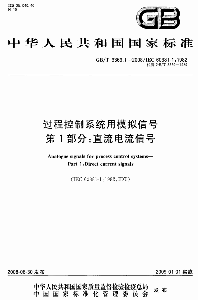
Analogue Signals for Process Control Systems – Part 2: Direct Voltage Signals (GB/T 3369.2—2008/IEC 60381-2:1978)
IEC 60381-2-1978, IDT

Preface
GB/T 3369.2—2008/IEC 60381-2:1978 – Analogue Signals for Process Control Systems – Part 2: Direct Voltage Signals
The GB/T 3369 standard consists of the following two parts:
Part 1: Direct current (DC) signals
Part 2: Direct voltage signals
This document represents Part 2 of GB/T 3369.
It fully adopts IEC 60381-2:1978, Analogue Signals for Process Control Systems – Part 2: Direct Voltage Signals (English version).
According to GB/T 1.1—2000 (Standardization Work Guide – Part 1: Standard Structure and Writing Rules), the following editorial modifications were made to IEC 60381-2:1978:
a) The term “this standard” was changed to “this part.”
b) The preface of IEC 60381-2:1978 was removed.
c) Any reference to “IEC 60381” was replaced with “GB/T 3369.”
d) The decimal comma “,” was replaced with a decimal point “.”
This part replaces GB/T 3370—1989 (Analog DC Voltage Signals for Industrial Automation Instruments).
Main Changes Compared to GB/T 3370—1989:
The standard name was changed from “Analog DC Voltage Signals for Industrial Automation Instruments” to “Analogue Signals for Process Control Systems – Part 2: Direct Voltage Signals.”
The term “this standard” was replaced with “this part.”
Scope of Application:
GB/T 3370–1989 was based on IEC 60381-2:1979 and applied to industrial automation instruments.
GB/T 3369.2—2008 is an equivalent adoption of IEC 60381-2:1979 and applies to industrial process measurement and control systems.
The term “industrial automation instruments” was changed to “components.”
The “ripple content” and “output AC component” definitions were removed, while new definitions were added for:
“Measured value of an analogue direct voltage signal”
“Load impedance”
“Ripple content”
“Signal common”
“Signal isolation”
Table 1 now includes signal ranges 0 to +10V and -10 to +10V.
Responsible Organizations:
Proposed by: China Machinery Industry Federation
Managed by: National Technical Committee on Industrial Process Measurement and Control Standardization (Second Subcommittee)
Drafting Institutions: Southwest University, China Silian Instrument Group
Participating Institutions:
China Machinery Industry Instrument and Economic Research Institute
Beijing Institute of Automation of Machinery Industry
Main Drafting Personnel: Liu Feng, Pan Dongbo, Zhang Yu, Liu Jin
Contributors: Feng Xiaosheng, Xie Bingbing
This part replaces previous standards:
GB 3370—1982
GB/T 3370—1989
Analogue Signals for Process Control Systems – Part 2: Direct Voltage Signals
1. Scope
This part applies to analogue direct voltage signals used for information transmission between system components in industrial process measurement and control systems.
Unlike the analogue direct current signals specified in GB/T 3369.1-2008, analogue direct voltage signals should not be used for long-distance transmission.
This part does not apply to signals used entirely within a single component.
2. Terms and Definitions
2.1 Components of Industrial Process Measurement and Control Systems
Functional units and integrated combination devices used to convert, transmit, or process measured values, control quantities, controlled variables, and reference variables.
2.2 Analogue Direct Voltage Signal
A DC voltage signal that varies continuously based on one or more physical quantities, used for information transmission or processing.
2.3 Measured Value of an Analogue Direct Voltage Signal
The average value of an analogue direct voltage signal over a specified duration.
2.4 Lower Limit
The minimum voltage value of the analogue direct voltage signal.
2.5 Upper Limit
The maximum voltage value of the analogue direct voltage signal.
2.6 Range of an Analogue Direct Voltage Signal
The range defined by the lower limit and upper limit of the signal voltage.
2.7 Load Impedance
The total impedance of all connected receivers.
2.8 Ripple Content
The ratio of the peak-to-peak value of the AC component to the upper limit of the analogue direct voltage signal.
2.9 Signal Common
A common electrical connection shared by multiple signal circuits, which may or may not be grounded.
2.10 Signal Isolation
The absence of electrical connections between the signal circuit and other circuits or the ground.
3. Technical Requirements
3.1 Range of Analogue Direct Voltage Signals
Table 1 provides the standard voltage signal ranges.
| Lower Limit (V) | Upper Limit (V) |
|---|---|
| +1 | +5 |
| 0 | +5 |
| 0 | +10 |
| -10 | +10 |
Notes:
Voltage signals can be derived from analogue direct current signals specified in GB/T 3369.1—2008.
Voltage signals can represent physical quantities using bipolar characteristics.
3.2 Ripple Content
When using ripple-free DC power supplies, the following should be specified:
Ripple content and frequency within the system components.
Noise and frequency generated within the system components.
Ripple content caused by DC power supply ripple should also be specified.
3.3 Signal Common Line
For unipolar signals, the negative terminal serves as the signal common line. If connected to a DC power supply, it should connect to the negative terminal of the power supply.
For bipolar signals, the neutral terminal serves as the signal common line. If connected to a DC power supply, it should connect to the neutral terminal of the power supply.
3.4 Grounding
For unipolar signals, if the component is grounded, the negative terminal of the signal and/or DC power supply should also be grounded.
For bipolar signals, if the component is grounded, the neutral terminal of the signal and/or DC power supply should be grounded.


 鄂公网安备 42018502006527号