


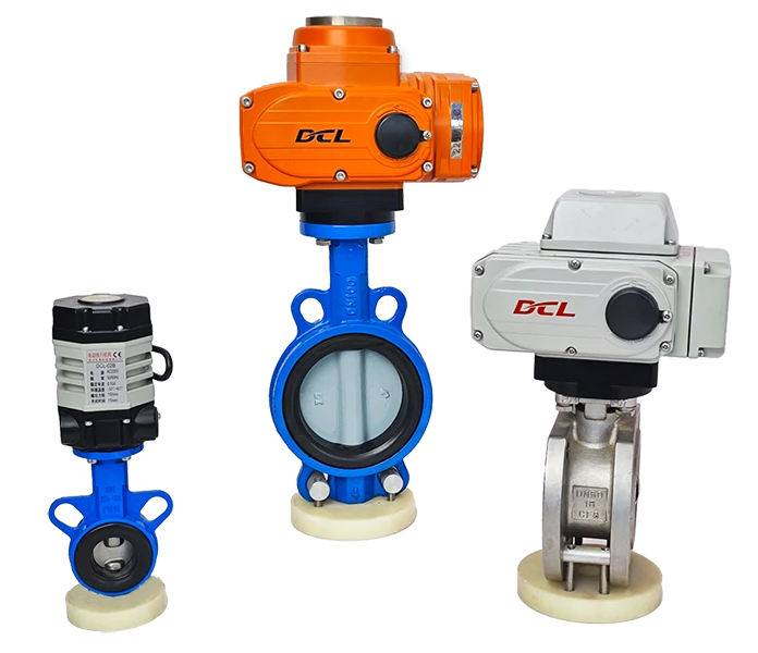
This guide applies to the modulating actuators of the DCL explosion-proof series, weather-proof series, and quick-turn series. The models are as follows:
Weather-proof actuator: DCL-05, DCL-10, DCL-20, DCL-40, DCL-60, DCL-100, DCL-160, DCL-250
Explosion-proof actuator: DCL-Ex05, DCL-Ex10, DCL-Ex20, DCL-Ex40, DCL-Ex60
Quick-turn actuator: DCL-K05, DCL-K10, DCL-K20, DCL-K40, DCL-K100
Common Faults and Fault Exclusion Methods
| Fault | Possible Causes | Fault Exclusion Methods |
|---|---|---|
| Actuator does not open or close at startup | 1. Incorrect wiring. 2. Incorrect power supply. 3. SA not set to 1 or 3 position. 4. Emergency stop switch is off (for actuators with emergency stop feature). 5. Input signal out of range. 6. Full open/close set to the same position. | 1. Check wiring against the actuator’s wiring diagram. 2. Verify the power supply voltage is within ±10% of the actuator’s rated voltage, and the current is at least three times the rated current. 3. Check and set the SA switch to position 1 or 3. 4. Check and turn on the emergency stop switch. 5. Measure the voltage between control module P3 and P4 with a multimeter. For current signal: 0.88V |
| Actuator stops before reaching target position | 1. Valve is stuck. 2. Solid particles in the fluid causing blockage. 3. Incorrect full open/full close position. 4. Incorrect input signal range calibration. | 1. Check for valve blockage. Clear the obstruction and retry after actuator cools down from overload protection. 2. Inspect fluid for particles causing valve blockage, clear blockage, and retry. 3. Refer to the “How to Set Control-type Electric Valves?” section for correct full open/close position settings. 4. Refer to the “How to Set Control-type Electric Valves?” section to calibrate the input signal range. |
| Cannot turn the actuator with the handwheel | 1. Solid particles in the fluid causing valve blockage. 2. Valve is stuck. 3. Actuator reduction mechanism is damaged. | 1. Inspect for blockage or solid particles causing valve issues, clear and retry after cooling. 2. Check if the valve is stuck. Clear any blockages and retry. 3. Remove the actuator from the valve. If the handwheel cannot turn, replace with a new actuator. |
| Incorrect feedback signal | 1. Open circuit. 2. Input impedance of the feedback signal receiver is too high. 3. Incorrect feedback signal calibration. | 1. Measure the voltage between control module P5 and P6 with a multimeter. If the value is >18V, it indicates an open circuit. Inspect and repair wiring. 2. Measure and confirm the input impedance of the feedback signal receiver is <800 ohms. 3. Refer to the “How to Set Control-type Electric Valves?” section for correct output current calibration. |
Check if Operating Conditions Meet Parameter Requirements
Electric actuators may malfunction or fail if used improperly or in incorrect operating conditions. To ensure long-term, trouble-free operation of the actuator, it is crucial to follow the operating conditions defined in the product specifications.
| Parameter | Requirement |
|---|---|
| Supply Voltage | The supply voltage must be within the actuator’s rated operating voltage range. Overvoltage or undervoltage may reduce the actuator’s lifespan. |
| Supply Current | Since the motor’s starting current is much higher than the rated current, ensure that the power supply’s output current capacity is at least three times the actuator’s rated current to ensure reliable operation. |
| Temperature | Ensure that the actuator operates within the rated working temperature range. Using the actuator in environments outside this range may cause malfunction, reduced lifespan, and eventually failure. |
| Environment | The DCL switch-type actuator has an IP67 weatherproof rating, suitable for both indoor and outdoor applications. It provides protection against rain and splashing water. Protecting the actuator from rain, snow, ice, and UV (sunlight) will typically extend its lifespan. Extremely corrosive environments may cause early failure of electronic components. Do not use non-explosion-proof actuators in explosive environments. |
| Duty Cycle | The duty cycle for DCL switch-type actuators is 70% (42 seconds of operation per minute, with 18 seconds off). A duty cycle exceeding 70% will trigger the motor’s overheat protection. |
This table ensures that the actuator is used under the correct conditions to maximize its longevity and performance. Let me know if you need further information!
3、Check that the actuator is wired correctly
E - Modulating with a control unit
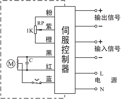
- Input: 4~20mA / 0~10V
- Output: 4~20mA / 0~10V
- Field Bus:Modbus / CAN
- IIot:WIFI/LoRA/4G DTU
Connecting Details:
- Connecting AC85-220V supply power line to L and neutral to N.
- Connecting 4-20mA/2-10V input signal source from control system to input-/+.
- Connecting Output -/+ to the system to send out the real-time valve position.
Note:
- The circuit inside the dashed box is the internal circuit of actuator. While the circuit outside is a demonstration of electrical connection for using actuator.
- If you have other specific requirements about connecting circuit, please feel free to contact our technical support.
When you are troubleshooting at the project site, you can contact our technical service personnel immediately to work together in identifying the fault and determining the solution.
Contact number: 13026331611 (Engineer Chen)


 鄂公网安备 42018502006527号