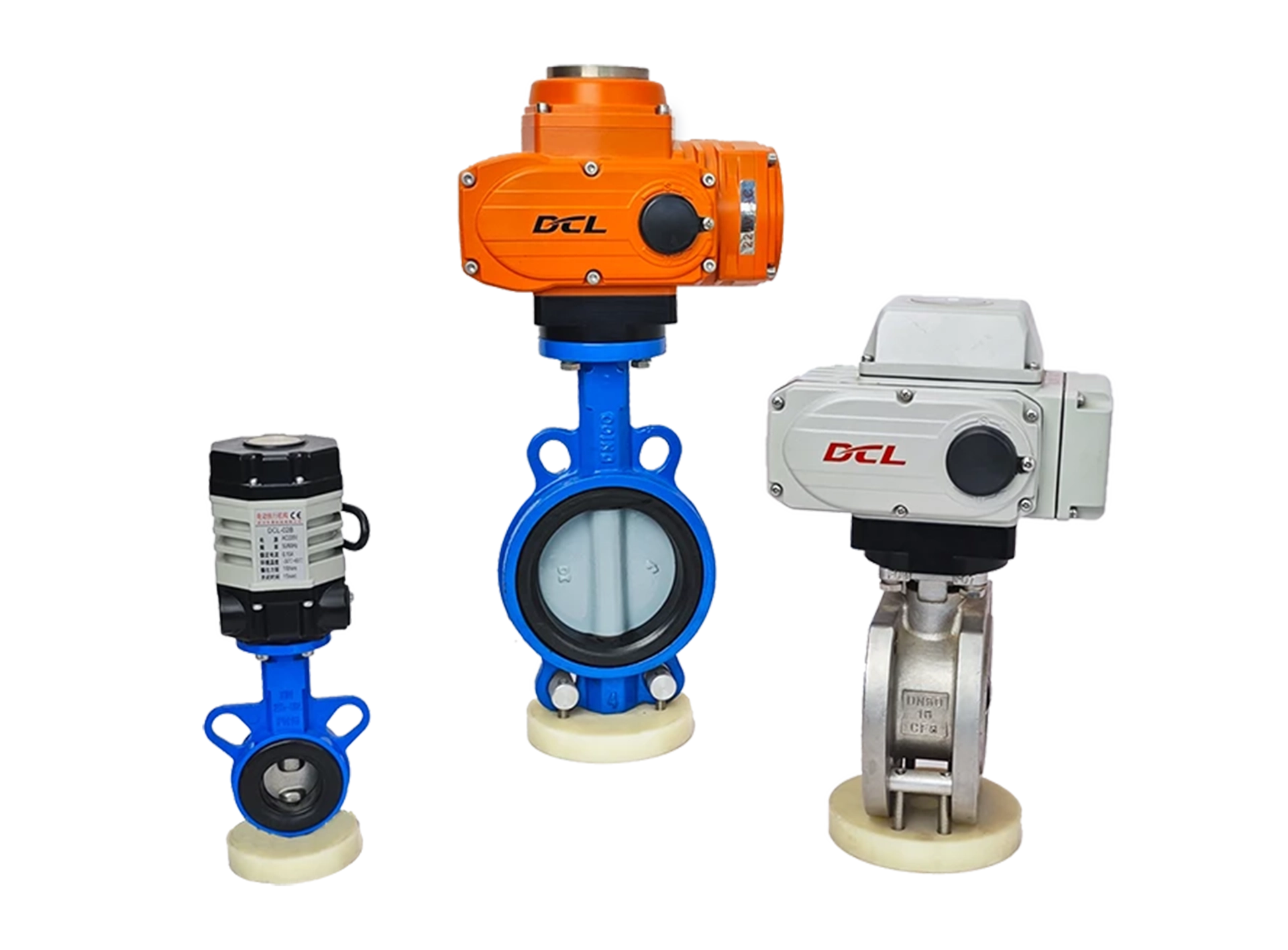
The standard for the 4-20mA current signal used in electric actuators is as follows:
Standard:
GB/T 3369.1—2008/IEC 60381-1:1982
Title: Analogue signals for process control systems — Part 1: Direct current signals (IEC 60381-1:1982, IDT)
This standard defines the specifications for analog signals, specifically for the use of direct current (DC) signals in process control systems, which includes the 4-20mA current signal commonly used in electric actuators.
Preface
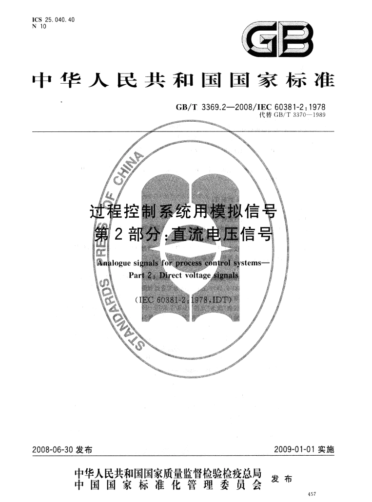
Foreword
GB/T 3369 “Analog Signals for Process Control Systems” is divided into the following two parts:
Part 1: Direct Current (DC) Current Signals;
Part 2: DC Voltage Signals.
This part is Part 1 of GB/T 3369.
This part is identical to IEC 60381-1:1982, titled “Analog signals for process control systems – Part 1: Direct current signals” (English version).
According to GB/T 1.1-2000 “Guidelines for Standardization – Part 1: Structure and Drafting Rules,” the following editorial modifications have been made to IEC 60381-1:1982:
“This standard” has been changed to “this part”;
The preface of IEC 60381-1:1982 has been removed;
Wherever “IEC 60381” appears, it has been changed to “GB/T 3369”;
The decimal point “.” has been used instead of the comma “,” for decimals.
This part replaces GB/T 3369-1989 “Analog DC Current Signals for Industrial Automation Instruments”.
Main Differences Compared to GB/T 3369-1989:
The title has changed from “Analog DC Current Signals for Industrial Automation Instruments” to “Analog Signals for Process Control Systems – Part 1: Direct Current Signals.”
“This standard” has been changed to “this part.”
The scope: GB/T 3369-1989 referred to IEC 60381-1:1982 and applied to industrial automation instruments. This standard, in contrast, refers to IEC 60381-1:1982 and applies to industrial process measurement and control systems (Chapter 1 of GB/T 3369-1989 vs Chapter 1 of this part).
The term “industrial automation instruments” has been changed to “elements” (Chapter 1 of GB/T 3369-1989 vs Chapter 1 of this part).
New definitions have been added, including “power supply” and “ripple content of the power supply voltage” (Sections 2.9, 2.10 of this part).
The technical requirements section has been updated to include “power supply” requirements (Section 3.7 of this part).
This part was proposed by the China Machinery Industry Federation.
This part was under the jurisdiction of the National Technical Committee 168 on Industrial Process Measurement and Control Standardization, Sub-Committee 2.
Drafting units: Southwest University, China Siliang Instrument and Meter Group.
Participating drafting units: Mechanical Industry Instrument and Meter Comprehensive Technology and Economic Research Institute, Beijing Mechanical Industry Automation Research Institute.
Key drafter: Liu Feng, Zhang Jiancheng, Zhu Peijun, Liu Jin.
Participating drafter: Feng Xiaosheng, Xie Bingbing.
The previous releases of the standard that this part replaces are:
GB 3369-1982;
GB/T 3369-1989.
1. Scope
This part specifies the use of analog DC current signals for transmitting information between system elements in industrial process measurement and control systems. This part does not apply to signals used entirely within a single element.
2. Terms and Definitions
The following terms and definitions apply to this part:
2.1 Elements of industrial process measurement and control systems
Functional units and their integrated combinations that convert, process, or transmit measurement values, control variables, controlled variables, and reference variables.
2.2 Analog direct current signal
A direct current signal used for transmitting information in industrial process measurement and control systems that continuously varies within its specified range.
2.3 Range of an analog direct current signal
All values within the defined limits.
2.4 Lower limit
The minimum value of the defined range.
Note: The lower limit can be zero or a finite value. If it is zero, it is called “true zero.” If it is a finite value, it is called “live zero.”
2.5 Upper limit
The maximum value of the defined range.
2.6 Load impedance
The total impedance of all connected receiving elements and wiring in the signal circuit.
2.7 Ripple content of the direct current signal
The ratio of the peak-to-peak value of the alternating component to the range of the analog DC current signal.
2.8 Signal circuit common
Multiple signal circuits may share a common electrical connection, which can either be grounded or not.
2.9 Power supply
The direct current power source that enables system elements to generate the DC current signal.
2.10 Ripple content of the power supply voltage
The ratio of the peak-to-peak value of the alternating component to the actual power supply voltage.
3. Technical Requirements
3.1 Range of Analog DC Current Signal
Table 1 provides the range for the analog DC current signal.
Table 1: DC Current Signal Range
| Lower Limit (mA) | Upper Limit (mA) |
|---|---|
| 4 (a) | 20 (b) |
| 0 | 20 (b) |
(a) Preferred value.
(b) Non-preferred value, to be phased out in the future.
3.2 Values Outside the Analog DC Current Signal Range
For the preferred signal, the value of 0mA is reserved exclusively for indicating a signal circuit fault or power supply failure.
3.3 Ripple Content of DC Current Signal
The ripple content of the signal should be specified and should not exceed 3%.
For systems that take instantaneous values from the signal (such as quick multi-channel input digital systems), the ripple content of the system element should be specified.
3.4 Signal Common Line
The signal common line should be the lowest potential point in the signal circuit. If the signal common line is connected to the power supply, it should be connected to the negative terminal of the power supply (or the 0V terminal of a bipolar power supply).
3.5 Grounding
If grounding is required for the signal circuit, the signal common line or the negative terminal of the power supply (or the 0V terminal of a bipolar power supply) should be grounded.
3.6 Load Impedance
A transmitter or control system element should be able to continuously drive any load between 0Ω and 300Ω.
3.7 Power Supply
Any transmitter system element using an external power supply should function properly with a power supply voltage range of 20 V(D.C.) to 30 V(D.C.).
The ripple content of the power supply voltage should be specified and should not exceed 10% of the nominal power supply voltage.
A stable power supply should be used.
For evaluating and comparing system element characteristics, it is recommended to use a 24 V(D.C.) reference power supply voltage.












 鄂公网安备 42018502006527号