


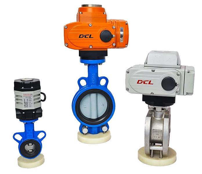
This guide is applicable to the DCL Explosion-proof Series / Weather-proof Series / Quick-Turning Series of modulating actuators powered by DC24V, with the following models:
Weather-proof Actuator: DCL-02GEY, DCL-05GEY, DCL-10GEY, DCL-20GEY, DCL-40GEY, DCL-60GEY
Explosion-proof Actuator: DCL-Ex05GEY, DCL-Ex10GEY, DCL-Ex20GEY, DCL-Ex40GEY, DCL-Ex60GEY
Let me know if you need further assistance with this guide!
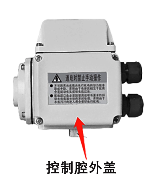
Open the Electric Chamber Cover
Use a Phillips screwdriver to unscrew the 4 fastening screws on the control chamber outer cover.
Check the Status of the Fault Indicator Light
2. Check the Fault Indicator Light Status
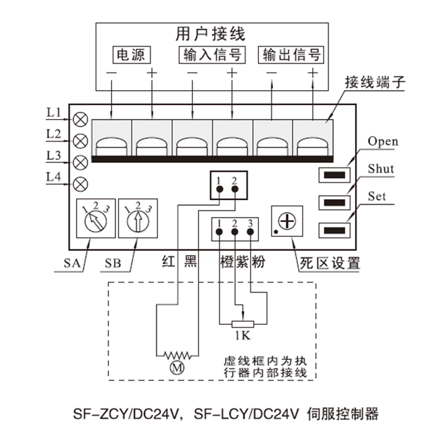
Keep the power on and check the fault indicator lights on the actuator control module (Model: SF-ZCY):
L1: Green – Power indicator. The light is on when the power supply is connected to the servo controller’s power terminals (–, +).
L2: Red – Input signal failure indicator. The light is on when the input signal fails.
L3: Red – Position detection circuit fault indicator. The light is on when there is an open circuit, short circuit, or damage to the position potentiometer leads.
L4: Red – Jam fault indicator. The light is on when a mechanical jam occurs.
Fault Diagnosis Logic:
L2 On: If the input signal is less than 2.5mA or greater than 22mA, the servo controller considers the input signal to have failed. Measure the voltage between the input signal terminals. For a 4~20mA input signal, the voltage across the input signal terminals should be between 0.88V and 4.4V. If the input signal is less than 0.55V (corresponding to 2.5mA) or greater than 4.84V (corresponding to 22mA), this indicates an open circuit, short circuit, leakage, or incorrect signal from the control system. If the voltage between the terminals is normal but L2 is still on, there may be a fault in the servo controller.
L3 On: Indicates a position detection circuit fault. Check if the potentiometer leads are open, shorted, or if the potentiometer itself is damaged. Normally, the voltage across the potentiometer should be around 4V, and the voltage between the potentiometer’s centerline and either end should change as the potentiometer’s angle changes. If all checks are normal but L3 is still on, there may be a fault in the servo controller.
L4 On: Indicates a mechanical failure during operation. Check if the motor wiring is loose or open. Verify if the motor itself is functioning properly. Use the handwheel to turn the actuator in both directions and check if there is any jam. If all checks are normal but L4 is still on, there may be a fault in the servo controller.
Signal Measurement
- Measure the DC 24V power supply voltage to check if there are any fluctuations or voltage drops in the actuator’s power supply. In a negative pressure state, the actuator’s output torque may decrease, which could prevent the valve from being driven.
- Measure the voltage between the input signal terminals (– and +).
- Measure the voltage between the output signal terminals (– and +).
- Apply an external signal, and during the actuator’s operation, measure the DC 24V power supply voltage. (This will help confirm the DC 24V power supply’s driving capability and any voltage drop in the cables.)
When troubleshooting at the project site, you can immediately contact our technical service personnel to work together in identifying the fault and determining a solution.
Contact number: 13026331611 (Engineer Chen)


 鄂公网安备 42018502006527号