Comparison of Interference Resistance Performance: 4-20mA VS. 2-10V
In the application of electric actuators’ anti-interference performance, the 4-20mA analog signal significantly outperforms the 2-10V analog signal. Why is this the case? 2-10V Signal Analysis Anti-interference Diagram for 2-10V Signal (DCL Huayi Intelligent Control) As shown in the diagram above: When using 2-10V, due to the higher input resistance
Common Used Buses for Electric Actuators
An increasing number of industrial control systems are deploying field buses to control more sensors and actuators. As a key actuator in fluid control processes, electric actuators are commonly used in industrial applications. The most frequently used bus systems for electric actuators include Modbus, CAN, Profibus, DeviceNet, Foundation Fieldbus, HART,
When to Choose a Process Control Actuator?
Application Background of Process Control Actuators In many process control systems, it is necessary to achieve highly accurate and consistent control of the flow rate of liquids or gases through an automated control system (PLC/DCS). Due to the high precision required, such systems often need to make continuous and precise
Electromagnetic Interference Testing for Electric Actuators (EFT)
The Increasingly Harsh Electromagnetic Environment in Industrial Sites As industrial electrification and intelligence continue to advance, an increasing number of high-power electrical devices (such as kilowatt-level motors, frequency converters, and inverters) are being integrated into industrial process control systems. Consequently, the electromagnetic environment in industrial sites is becoming more complex.
Common Types of Valves and Their Features
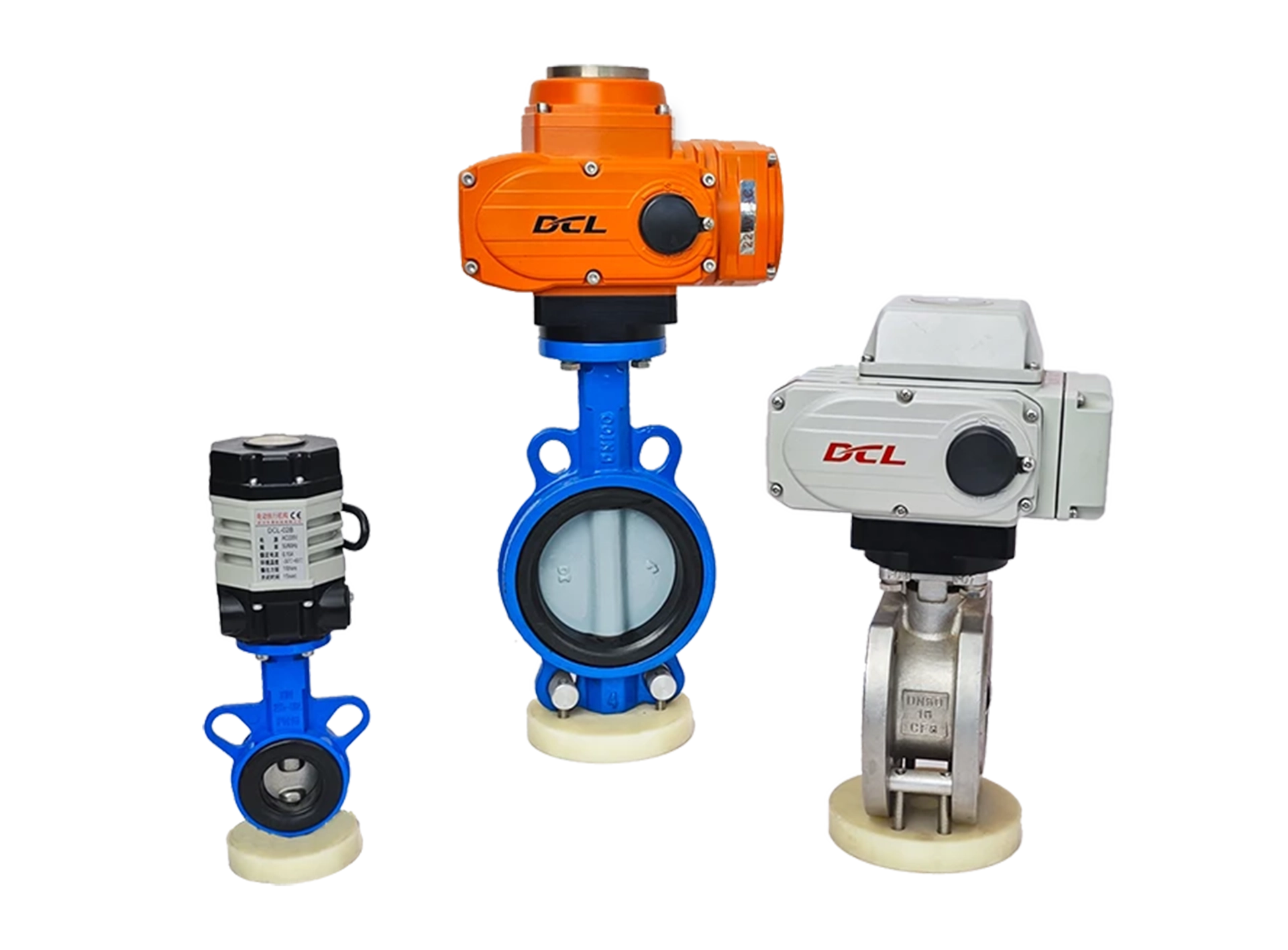
Butterfly Valve Working Principle: A butterfly valve uses a disc to control the flow of fluids or gases. The disc is mounted on a shaft, and when the handle is turned, the disc rotates 90 degrees to allow or block the flow. Features: Simple structure, compact size, low flow resistance,
How Actuators with Bus Functions Work – Modbus, CAN, Ethernet, Profibus
When you install a DCL electric control valve with bus functionality on a pipeline, you can control a set of electric control valves through the bus (Modbus, CAN, Ethernet, Profibus) to achieve synchronized control of the valve cluster. The control system communicates with the actuator via a bus communication protocol,
How the DC24V ON-OFF Type Actuator (Electric Valve) Works
When you install a DCL 24V ON-OFF type electric control valve on a pipeline, you can control it using a relay, ON-OFF control, or PLC (DCS), enabling the opening or shutting off of fluid flow. This guide explains how the DCL 24V ON-OFF type electric actuators function using relays, PLCs,
How the AC220V ON-OFF Type Actuator (Electric Valve) Works
When you install a DCL AC220V ON-OFF type electric control valve on a pipeline, you can control it using a relay, ON-OFF control, or PLC (DCS), enabling the opening or shutting off of fluid flow. This guide explains how the DCL AC220V ON-OFF type electric actuators function using relays, PLCs,
Types of Actuators and How to Choose the Right One
Actuators can be classified based on their driving method into the following categories: 1. Electric Actuators Electric actuators use an electric motor as the power source, converting electrical energy into mechanical motion to drive the valve. Advantages: ✔ Adjustable speed✔ High positioning accuracy✔ Large torque output Disadvantages: ✖ Thermal effects
How Humidity Reduces the Lifespan of Actuators (Electric Valves)?
Humidity is well known to cause damage to electronic components. One of the primary ways humidity reduces the lifespan of electric actuators is through ionic migration short circuits. 1. What is Ionic Migration Short Circuit? Ionic migration occurs when moisture and contaminants on a circuit board facilitate the movement of
What Does the S2 Duty Cycle Mean in Actuators (Electric Valves)?
Many people have questions about the S2 duty cycle in actuators or electric valves. What does it mean, and why is it defined this way? 1. The Origin of S1, S2, S3, and S6 Duty Cycles The S1, S2, S3, and S6 duty cycles originate from electric motor classifications, with
Why Do Voltage Output Signals Oscillate in Certain Conditions?
1. Voltage Signal Transmission Path As shown in Figure 1, a voltage signal transmission system consists of three key components: Negative feedback voltage output circuit Signal transmission cable Includes parasitic capacitance (C1) and parasitic inductance (L1), which depend on cable length and wiring layout. Input signal acquisition circuit May
How to choose a suitable DC brushless motor?
我在产品设计中,需要使用无刷电机了。 网上各种型号的参数表太分散了,难道没有一款包含所有型号参数的对照表吗? 有的,这张表正是你需要的。









 鄂公网安备 42018502006527号