


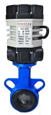
This guide applies to the DCL ultra small modulating actuators, model as follows:
DCL-02E
Common Faults and Troubleshooting Methods
| Fault | Possible Cause | Troubleshooting Method |
|---|---|---|
| Actuator will not open or close at startup | 1. Incorrect wiring | Check the wiring according to the actuator wiring diagram to confirm it is correct. |
| 2. Incorrect power supply | Ensure the power supply output voltage is within ±10% of the actuator’s rated voltage, and the current is 3 times the actuator’s rated current. | |
| 3. Abnormal control switch or relay | Measure the input voltage at the actuator’s switch control terminal with a multimeter to ensure it matches the expected value. | |
| 4. Control system mismatch | Use a mechanical switch to test the actuator’s functionality. If the actuator runs correctly, verify the control system output logic. | |
| 5. Multiple actuators or actuator parallel connection with other devices | Switch-type actuators start with a capacitor. Parallel connection with other devices will affect the capacitor’s value. Switch-type actuators should only use single control, not parallel control. | |
| Actuator can only open or close | 1. Incorrect wiring | 1. Use a mechanical switch to test the actuator’s functionality. If it runs correctly, verify the control system output logic. |
| 2. Check wiring according to the actuator’s wiring diagram. | ||
| 2. Incorrect full-open/full-close cam setting | Refer to “How to Set Switch-type Electric Valves” for proper cam positioning. | |
| Actuator stops mid-stroke | 1. Valve jamming | Check if the valve is jammed, clear the blockage, and retry after the actuator’s overload protection cools down. |
| 2. Solid particles in the fluid causing valve jamming | Check if solid particles in the fluid are causing the valve to jam, clear the blockage, and retry after the actuator’s overload protection cools down. | |
| 3. Incorrect full-open/full-close stop block setting | Refer to “How to Set Switch-type Electric Valves” to adjust the stop block position properly. | |
| Cannot rotate actuator using the handle | 1. Solid particles in the fluid causing valve to seize | Check if solid particles are causing the valve to seize, clear the blockage, and retry after the actuator’s overload protection cools down. |
| 2. Valve is stuck | Check if the valve is stuck, clear the blockage, and retry after the actuator’s overload protection cools down. | |
| 3. Actuator deceleration mechanism damaged | Remove the actuator from the valve, rotate the handle. If it doesn’t rotate, replace it with a new actuator. | |
| No output from position feedback signal | 1. Incorrect switch wiring | Check the wiring according to the actuator’s wiring diagram to confirm it is correct. |
| 2. Incorrect full-open/full-close cam setting | Refer to “How to Set Switch-type Electric Valves” to adjust the cam position properly. | |
| 3. Overcurrent causing position feedback switch failure | 1. Refer to “How to Set Switch-type Electric Valves” to check if the full-open/full-close cam is properly pressing the position feedback switch. | |
| 2. Measure if the position feedback circuit is connected. |
2. Verify Application Conditions for Compatibility
Electric actuators can fail if they are used improperly or under incorrect application conditions. Ensuring that the actuator operates within the specifications defined in the product datasheet will help ensure long-term, trouble-free operation.
Power Supply Voltage: The voltage from the power supply must be within the actuator’s rated operating voltage range. Overvoltage or undervoltage may reduce the actuator’s lifespan.
Power Supply Current: Since the motor’s starting current is much higher than the rated current, ensure that the power supply has at least 3 times the rated current capacity of the actuator.
Temperature: Ensure the actuator operates within its rated temperature range. Using the actuator outside of the rated temperature range can lead to malfunction or reduced lifespan, ultimately causing failure.
Environment: DCL switch-type actuators are rated IP67 for weather resistance, suitable for both indoor and outdoor use. They offer some protection against rain, splashing water, and UV (sunlight), which typically extends the product’s life. However, highly corrosive environments can cause early failure of the electronic components. Do not use non-explosion-proof series actuators in hazardous environments.
Duty Cycle: The DCL switch-type actuator has a duty cycle of 70% (42 seconds of operation followed by 18 seconds of rest). Exceeding this duty cycle may cause the motor to enter thermal protection mode.
Check the Wiring of the Actuator
To ensure proper operation of the actuator, follow these steps:
Verify the Wiring According to the Diagram:
Double-check the wiring to ensure it matches the actuator’s wiring diagram.
Confirm that all connections are secure and that no wires are loose or disconnected.
Check for Correct Polarity:
Ensure that the power supply’s positive and negative terminals are connected to the correct actuator terminals.
Incorrect polarity can lead to malfunction or damage to the actuator.
Inspect the Control Signal Wiring:
Verify the wiring for the control signals (e.g., input signal, feedback signal).
Make sure the signal wires are correctly connected and are free from short circuits or breaks.
Check for Grounding:
Ensure proper grounding of the actuator to avoid electrical noise interference or potential short circuits.
A faulty ground connection can cause erratic behavior or failure to operate.
Confirm the Wiring for External Components:
If external devices like limit switches, sensors, or additional control modules are connected, check that the wiring is secure and correct.
Test the Control Circuit:
Use a multimeter to check the control circuit, including the input voltage at the control terminals.
Confirm the expected voltage range is present.
After confirming the wiring is correct, proceed with testing the actuator to ensure it operates properly. If any issues persist after checking the wiring, further inspection of the actuator’s internal components may be necessary.
E - Modulating with a control unit
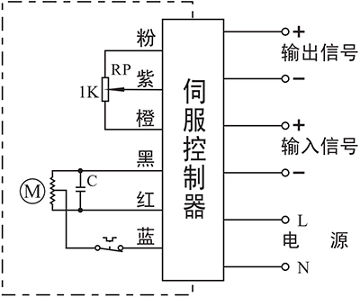
- Input: 4~20mA / 0~10V
- Output: 4~20mA / 0~10V
Connecting Details:
- Connecting AC85-220V supply power line to L and neutral to N.
- Connecting 4-20mA/2-10V input signal source from control system to input-/+.
- Connecting Output -/+ to the system to send out the real-time valve position.
Note:
- The circuit inside the dashed box is the internal circuit of actuator. While the circuit outside is a demonstration of electrical connection for using actuator.
- If you have other specific requirements about connecting circuit, please feel free to contact our technical support.
When troubleshooting on-site, you can contact our technical service team immediately to jointly troubleshoot the issue and determine the solution.
Contact number: 13026331611 (Mr. Chen)


 鄂公网安备 42018502006527号