1. Mechanical Installation
1. Mechanical Installation
Refer to the “How to Install the Actuator onto the Valve” section to correctly install the actuator onto the valve and manually operate it to confirm proper functioning.
Follow the guidelines in “How to Set the ON-OFF Electric Valve” to properly adjust the actuator’s electrical limits (close limit CLS and open limit OLS) and mechanical limits.
Important Notes:
Unless specified otherwise, the actuator’s stroke angle between the fully closed and fully open positions is typically 90° during factory debugging.
The output current corresponds to 4mA when fully closed and 20mA when fully open.
The position potentiometer has been calibrated during the valve matching process, accounting for potential position changes at full open and full close, so users should generally avoid adjusting the potentiometer and its gears.
Follow the wiring diagram below for correct terminal connections.
2. Position Transmitter Panel Explanation
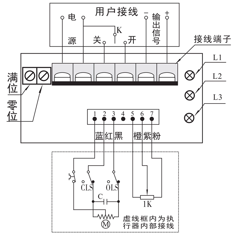
- Adjustable Potentiometers:
“Full Position” and “Zero Position” potentiometers are used to adjust the corresponding output current to 20mA or 4mA when the valve is fully open or fully closed, respectively.
Indicators:
L1 (Red): Power indicator, lights up when the position transmitter is powered on.
L2 (Green): Lights up when the valve is opening.
L3 (Green): Lights up when the valve is closing.
3. Debugging and Settings
- Potentiometer Mid-Position Determination
- Output Current Calibration:
The position transmitter is factory-calibrated and typically does not require user adjustment. However, if the output current at full open or full close is not 20mA or 4mA with an error greater than 1%, calibration is needed. The following steps can be followed for calibration:Connect a 20mA DC ammeter to the output signal terminal.
Set the valve to fully closed, then use a small flathead screwdriver to adjust the “Zero Position” potentiometer while observing the ammeter. Rotate the potentiometer clockwise if the current is greater than 4mA or counterclockwise if it is less, until the ammeter reads 4mA (±0.02).
Set the valve to fully open, then adjust the “Full Position” potentiometer in a similar manner, rotating it counterclockwise if the current is greater than 20mA or clockwise if it is less, until the ammeter reads 20mA (±0.02).
Output current calibration is complete.
Note:
Always adjust the “Zero Position” first and then the “Full Position” to avoid damaging the position transmitter.








 鄂公网安备 42018502006527号