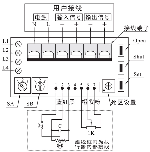
Turn the S-A switch to position 2.
Press and hold the Set button until the L2 red LED lights up. (After releasing, L2 will start flashing.)
Within 5 seconds, press and hold both the Open and Shut buttons simultaneously. L2 flashing will switch to L3 flashing, indicating that the control module has entered input signal calibration mode.
Apply a 4mA signal from the signal source, then press and hold Set and Shut simultaneously until L4 lights up, completing the 4mA calibration.
Apply a 20mA signal from the signal source, then press and hold Set and Shut simultaneously until L4 lights up, completing the 20mA calibration.
Finally, press and hold the Set button until L3 stops flashing and turns off, indicating that the module has exited calibration mode.


 鄂公网安备 42018502006527号

