




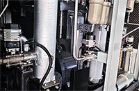



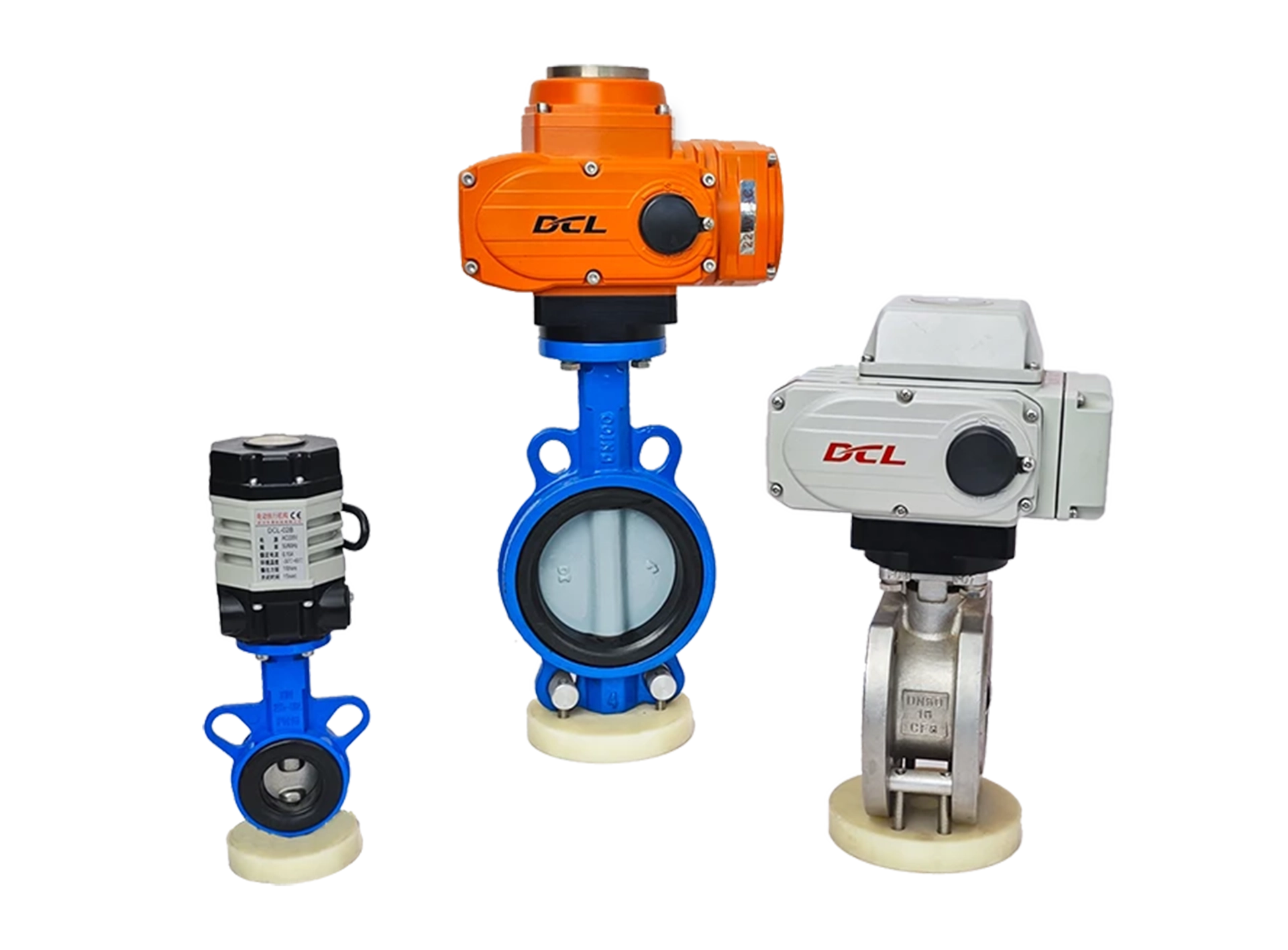
This guide applies to the switch-type actuators of the DCL explosion-proof series, standard series, and quick-open series. The models are as follows:
Weather-proof Actuator: DCL-05, DCL-10, DCL-20, DCL-40, DCL-60, DCL-100, DCL-160, DCL-250
Explosion-Proof Actuator: DCL-Ex05, DCL-Ex10, DCL-Ex20, DCL-Ex40, DCL-Ex60
Quick-Turn Actuator: DCL-K05, DCL-K10, DCL-K20, DCL-K40, DCL-K100
Common Faults and Troubleshooting Methods
| Fault | Possible Causes | Troubleshooting Methods |
|---|---|---|
| Actuator does not open or close at startup | 1. Incorrect wiring. 2. Incorrect power supply. 3. Faulty control switch or relay. 4. Control system mismatch. 5. Multiple actuators or actuator in parallel with other devices. | 1. Check the wiring against the actuator’s wiring diagram to ensure it is correct. 2. Verify power supply output voltage is ±10% of rated voltage, and the current is at least three times the actuator’s rated current. 3. Use a multimeter to measure input voltage at the actuator’s control terminal and confirm it matches expected values. 4. Use a mechanical switch to test actuator operation. If it works, verify the control system output logic. 5. Switch-type actuators should not be connected in parallel with other devices; use a single control circuit. |
| Actuator only opens or closes, not both | 1. Incorrect wiring. 2. Incorrect full open/full close cam settings. | 1. Use a mechanical switch to test actuator functionality. If it works, verify the control system output logic. 2. Check actuator’s wiring against the wiring diagram. 3. Adjust the cam settings according to the “How to Set Switch-type Electric Valves” manual. |
| Actuator stops in the middle of its stroke | 1. Valve is stuck. 2. Solid particles in the fluid medium causing valve blockage. 3. Incorrect full open/full close block settings. | 1. Check if the valve is stuck. Remove obstructions and retry after the actuator cools down from overload protection. 2. Inspect the fluid medium for solid particles. Remove any blockage and retry after cooling. 3. Adjust block settings according to the “How to Set Switch-type Electric Valves” manual. |
| Cannot turn the actuator with the handwheel | 1. Solid particles in the fluid medium causing valve blockage. 2. Valve is stuck. 3. Actuator’s reduction mechanism is damaged. | 1. Check fluid medium for particles causing blockage. Remove obstructions and retry after cooling. 2. Inspect valve for any stuck parts. Remove blockage and retry. 3. If actuator cannot be turned by hand, remove it from the valve. If it still doesn’t turn, replace with a new actuator. |
| No output from position feedback signal | 1. Incorrect switch wiring. 2. Incorrect full open/full close cam settings. 3. Overcurrent causing damage to the position feedback signal switch. | 1. Check wiring of the switch against the actuator’s wiring diagram to ensure it is correct. 2. Verify full open/full close cam is properly compressing the position feedback switch. 3. Measure the position feedback circuit to check if the switch is intact and properly connected. |
Please check if the operating conditions meet the parameter requirements.
Electric actuators may fail due to improper use or operating in incorrect conditions. To ensure long-term, trouble-free operation, the actuator must be used within the operating conditions specified in the product datasheet.
Power Supply Voltage: The supply voltage must be within the actuator’s rated operating voltage range. Overvoltage or undervoltage may reduce the actuator’s lifespan.
Power Supply Current: Since the motor’s starting current is significantly higher than the rated current, please ensure that the power supply can provide a current capacity at least 3 times the actuator’s rated current to ensure reliable operation.
Temperature: Ensure that the actuator operates within the rated temperature range. Operating the actuator outside the specified temperature range may cause malfunction, reduced lifespan, or eventual failure.
Environment: The DCL switch-type actuators are rated at IP67 for wind and rain protection. They are generally suitable for both indoor and outdoor use, providing protection against rain, splashes, and UV exposure (sunlight), which typically extends the product’s lifespan. Extremely corrosive environments may cause premature failure of electronic components. Do not use non-explosion-proof actuators in explosive atmospheres.
Duty Cycle: The duty cycle of the DCL switch-type actuator is 70% (42 seconds of operation per minute, with a required 18 seconds off). Exceeding a 70% duty cycle will trigger thermal protection for the motor.
Check if the wiring of the actuator is correct.
Ensure that all electrical connections are properly made according to the wiring diagram provided in the product manual. Incorrect wiring can lead to malfunction or damage to the actuator. Verify the following:
The power supply connections are properly secured and there are no loose wires.
The control signal wiring is correctly connected, ensuring polarity and signal type are properly matched.
The ground connection (if applicable) is properly established to avoid electrical hazards.
Double-check the connection of any external components, such as limit switches or feedback devices, to ensure they are wired correctly.
דלוק - כבוי
A - עם 2 יציאות אות קצה פעילות
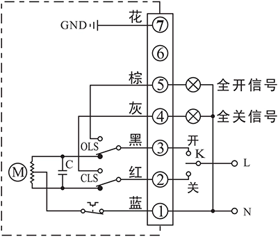
- בקרת מפעיל לפתיחה או סגירה באמצעות K
- מסוף הפלט של מיקום הקצה פתוח/סגור ישלח את האירוע כאות פעיל של 220VAC כאשר מיקום הקצה הושג.
פרטי חיבור:
- חיבור נקודת אפס של אספקת חשמל AC85-220V ל-P1.
- העבר את קו AC85-220V למצב CLOSE (P2) כדי לסגור את השסתום
- העבר את קו AC85-220V למצב OPEN (P3) כדי לפתוח את השסתום.
- P5 הוא הדק במצב קצה פתוח, אשר יפלוט מקור AC220V שניתן להשתמש בו כדי להפעיל נורית חיווי כאשר המפעיל מגיע למצב קצה של פתיחה.
- P6 הוא הדק פתוח במצב קצה, אשר יפלוט מקור AC220V שניתן להשתמש בו כדי להפעיל נורית חיווי כאשר המפעיל מגיע למצב קצה של סגירה.
- חבר את הארקה ל-P7.
B - עם 2 מתגי קצה פסיביים
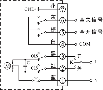
- בקרת מפעיל לפתיחה או סגירה באמצעות K
- מסוף הפלט של מיקום הקצה OPEN/CLOSE ישלח את האירוע כאות פסיבי כאשר מיקום הקצה הושג.
פרטי חיבור:
- חיבור נקודת אפס של אספקת חשמל AC85-220V ל-P1.
- העבר את קו AC85-220V למצב CLOSE (P2) כדי לסגור את השסתום
- העבר את קו AC85-220V למצב OPEN (P3) כדי לפתוח את השסתום.
- P4 הוא ה-COM עבור אות מגע פסיבי של מיקום קצה פתוח/סגור, אשר בדרך כלל מחובר לאות GND.
- P5 הוא הדק קצה פתוח אשר יחובר ל-COM כאשר המפעיל יגיע למצב קצה פתוח.
- P6 הוא הדק קצה סגור אשר יחובר ל-COM כאשר המפעיל יגיע למצב קצה סגירה.
- חבר את הארקה ל-P7.
מנוע DC עם 2 מתגי קצה

- בקר את המפעיל לפתיחה או סגירה לפי כיוון אספקת החשמל בין הדק 1 ו-2
- מסוף הפלט של מיקום הקצה OPEN/CLOSE ישלח את האירוע כאות פסיבי כאשר מיקום הקצה הושג.
פרטי חיבור:
- חיבור DC24V+ ל-P1 ו-DC24V- ל-P2 כדי לסגור את השסתום.
- חיבור DC24V+ ל-P2 ו-DC24V- ל-P1 כדי לסגור את השסתום.
- P3 הוא ה-COM עבור אות מגע פסיבי של מיקום קצה פתוח/סגור, אשר בדרך כלל מחובר לאות GND.
- P4 הוא הדק קצה פתוח, אשר יחובר ל-COM כאשר המפעיל יגיע למצב קצה פתוח.
- P5 הוא הדק קצה סגור אשר יחובר ל-COM כאשר המפעיל יגיע למצב קצה סגירה.
- חבר את הארקה ל-P7.
מנוע תלת פאזי 380VAC עם 2 מתגי קצה
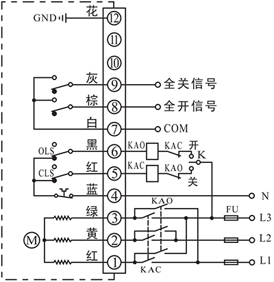
- מפעיל בקרה לפתיחה או סגירה באמצעות ממיר חיצוני לשינוי פאזה של אספקת החשמל.
- מסוף הפלט של מיקום הקצה OPEN/CLOSE ישלח את האירוע כאות פסיבי כאשר מיקום הקצה הושג.
פרטי חיבור:
- חיבור יציאת ממיר תלת פאזי AC380V ל-P1, P2 ו-P3, לאחר מכן ניתן לשלוט במפעיל לפתוח או לסגור את השסתום על ידי שינוי סדר התלת פאזי.
- חיבור ניטרלי AC380V ל-N(P4).
- P5 משמש לשיתוף פעולה עם מתג חיצוני לשליטה בסדר תלת פאזי של הממיר. מסוף זה מחובר ל-N(P4) כאשר המפעיל אינו במצב סגירה וניתק מ-N(P4) לאחר שהמפעיל מגיע למצב סגירה.
- P6 משמש לשיתוף פעולה עם מתג חיצוני לשליטה בסדר תלת פאזי של הממיר. מסוף זה מחובר ל-N(P4) כאשר המפעיל אינו במצב קצה פתוח ומתנתק מ-N(P4) לאחר שהמפעיל הגיע למצב קצה פתוח.
- P7 הוא ה-COM עבור אות מגע פסיבי של מיקום קצה פתוח/סגור, אשר בדרך כלל מחובר לאות GND.
- P8 הוא הדק קצה פתוח, אשר יחובר ל-COM כאשר המפעיל יגיע למצב קצה פתוח.
- P9 הוא הדק קצה סגירה אשר יחובר ל-COM כאשר המפעיל יגיע למצב קצה סגירה.
- חבר את הארקה ל-P12.
אינצ'ינג ומיקום
F - עם יחידת מיקום
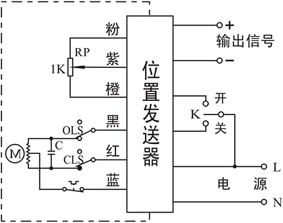
- בקרת מפעיל לפתיחה או סגירה באמצעות K
- מיקום השסתום בזמן אמת יישלח כאות של 4-20mA.
פרטי חיבור:
- חיבור קו אספקת חשמל AC85-220V ל-L וקו ניטרלי ל-N.
- העבר את קו AC85-220V למצב CLOSE (P2) כדי לסגור את השסתום.
- העבר את קו AC85-220V למצב OPEN (P3) כדי לפתוח את השסתום.
- חיבור פלט -/+ למערכת לשליחת מיקום השסתום בזמן אמת.
C - עם פוטנציומטר 1KΩ/500Ω
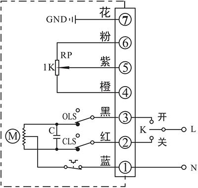
- בקרת מפעיל לפתיחה או סגירה באמצעות K
- מיקום השסתום בזמן אמת יישלח כערך התנגדות פוטנציומטר
פרטי חיבור:
- חיבור נקודת אפס של אספקת חשמל AC85-220V ל-P1.
- העבר את קו AC85-220V למצב CLOSE (P2) כדי לסגור את השסתום
- העבר את קו AC85-220V למצב OPEN (P3) כדי לפתוח את השסתום.
- P4 הוא הצד הנמוך של הפוטנציומטר שבדרך כלל מחובר לאות GND.
- חיבור קלט האות של מערכת הבקרה ל-P5. ערך ההתנגדות בין P4 ל-P5 יעלה ככל שהמפעיל יפתח את השסתום, בעוד שהערך בין P5 ל-P6 יקטן.
- P6 הוא הצד הגבוה של הפוטנציומטר שבדרך כלל מחובר לאות הספק.
- חבר את הארקה ל-P7.
D - עם פוטנציומטר ומשוב קצה
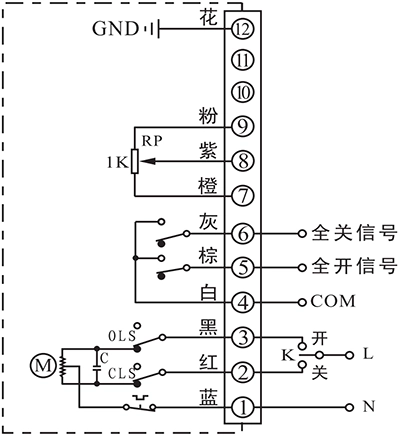
- בקרת מפעיל לפתיחה או סגירה באמצעות K
- מיקום השסתום בזמן אמת יישלח כערך התנגדות פוטנציומטר
- מסוף הפלט של מיקום הקצה OPEN/CLOSE ישלח את האירוע כאות פסיבי כאשר מיקום הקצה הושג.
פרטי חיבור:
- חיבור נקודת אפס של אספקת חשמל AC85-220V ל-P1.
- העבר את קו AC85-220V למצב CLOSE (P2) כדי לסגור את השסתום
- העבר את קו AC85-220V למצב OPEN (P3) כדי לפתוח את השסתום.
- P4 הוא ה-COM עבור אות מגע פסיבי של מיקום קצה פתוח/סגור, אשר בדרך כלל מחובר לאות GND.
- P5 הוא הדק קצה פתוח אשר יחובר ל-COM כאשר המפעיל יגיע למצב קצה פתוח.
- P6 הוא הדק קצה סגור אשר יחובר ל-COM כאשר המפעיל יגיע למצב קצה סגירה.
- P7 הוא הצד הנמוך של הפוטנציומטר שבדרך כלל מחובר לאות GND.
- חיבור קלט האות של מערכת הבקרה ל-P8. ערך ההתנגדות בין P7 ל-P8 יעלה ככל שהמפעיל יפתח את השסתום, בעוד שהערך בין P8 ל-P9 יקטן.
- P9 הוא הצד הגבוה של הפוטנציומטר שבדרך כלל מחובר לאות הספק.
- חבר את הארקה ל-P12.
פֶּתֶק:
- המעגל בתוך התיבה המקווקוות הוא המעגל הפנימי של המפעיל. בעוד שהמעגל החיצוני הוא הדגמה של חיבור חשמלי לשימוש במפעיל.
- אם יש לכם דרישות ספציפיות נוספות בנוגע לחיבור מעגל, אל תהססו לפנות לתמיכה הטכנית שלנו.


 English (UK)
  香港中文
香港中文  繁體中文
繁體中文  English (Canada)
  English (South Africa)
  English (Australia)
  English (New Zealand)
  English
  Español de Puerto Rico
  Français du Canada
  Español de México
  Español de Chile
  Español de Colombia
  Español de Uruguay
  עִבְרִית
  Nederlands (België)
  Français de Belgique
  Eesti
Eesti  Latviešu valoda
  Lietuvių kalba
  Français
  Deutsch
  Norsk nynorsk
  Deutsch (Österreich)
  Slovenčina
  Deutsch (Schweiz)
  Italiano