


DCL Actuator with FSR
Operation Panel
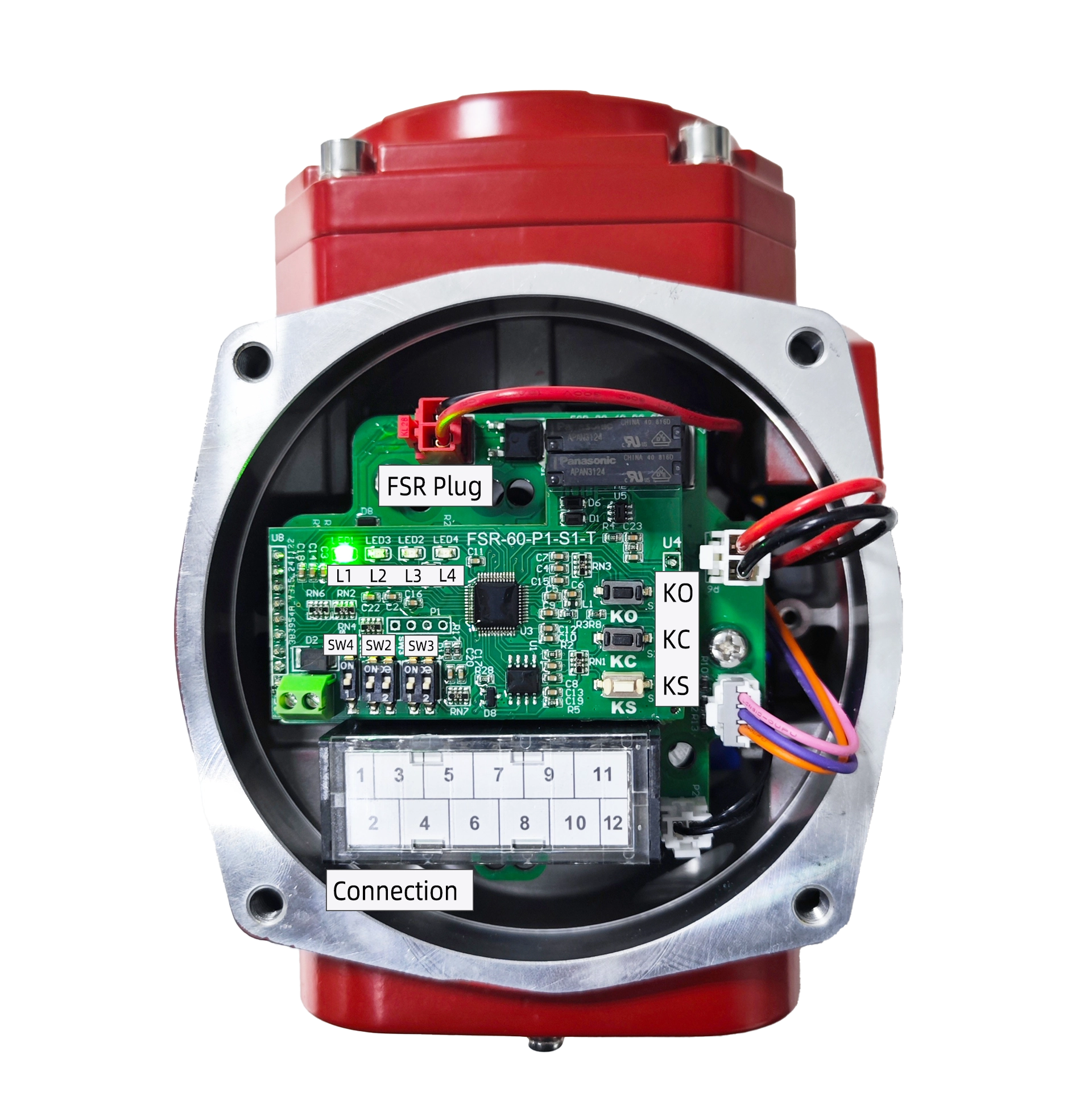
- Connection
P1:DC24V Power +
P3:DC24V Power –
P5:4-20mA Input –
P7:4-20mA Input +
P9:4-20mA Output –
P11:4-20mA Output +
P2:ON/OFF Input COM
P4:ON/OFF Input Open
P6:ON/OFF Input Close
P8:ON/OFF Output COM
P10:ON/OFF Output Open
P12:ON/OFF Output Close
- Button
KO: Used in setting mode. Press this button to open the actuator
while release it to stop. Press “Set” and “Open” simultaneously to
set the full open position.KC: Used in setting mode. Press this button to Shut the actuator
while release it to stop. Press “Set” and “Shut” simultaneously to
set the full shut position.KS: Used in setting mode. Combination use this button with
others to configure the parameters. - Switch
SA: Set operation mode (Default set to 1):
1–Normal Modulation 2–Setting Mode 3–Reverse Modulation
SB: Set Safety Position (Default set to 1):
1–Drive to Fully Open 2–Keep Position 3–Drive to Fully
Shut
- Indication
L1: Green, Power Indication;
L2: Red, Input signal error, turned on when input signal is over
range;L3: Red, Potentiometer error, turned on when potentiometer is
abnormal or connection wire is broken;L4: Red, Stuck error, turned on when actuator can not be driven
to open or close.
Settings
Switch SA to 2 to enter the setting mode. Then you can set the
operation rotation range, set the safety position, calibrate the input
and output signal and etc.
- Operation Range
Configure Fully Close Position:
- Press the Open/Shut button to drive the valve to the fully closed
position. - Hold the Set button and then the Shut button until L2 is turned on
about 3-4 seconds later which means the fully closed position
configuration is done. - Now you can release these 2 buttons.
Configure Fully Open Position:
- Press the Open/Shut button to drive the valve to the fully open
position. - Hold the Set button and then the Open button until L2 is turned on
about 3-4 seconds later which means the fully open position
configuration is done. - Now you can release these 2 buttons.
[Note: When the fully open and close position was configured with
the same position, the configuration will be done successfully. But
the actuator will not rotate in modulation mode.]{.underline}
- Set Safety Position
Set the safety position with SB as you wish when supply power was broken
down or input signal was fault.
- Turn S-B to 1 to let the actuator drive the valve to fully open
position. - Turn S-B to 2 to let the actuator keep the current valve position.
- Turn SB to 3 to let the actuator drive the valve to fully close
position.This part of configuration is normally unnecessary, reconfigure
these if it really matters.
- 4-20mA Output Calibration
- Turn S-A to 2
- Connect an ammeter to signal output to monitor current.
- Hold the set button then open and shut simultaneously until L2 is
turned on which means 4mA calibration mode being entered. Now you
could release these 3 buttons. - Press Open(increase) or Shut(decrease) to adjust 4mA.
- Hold the set button until L2 was turned off and on again, then
release the button to enter 20mA calibration. - Press Open(increase) or Shut(decrease) to adjust 20mA.
- Hold the set button until L2 was turned off and on again, then
release the button to complete the calibration process.
- 4-20mA Input Calibration
- Turn S-A to 2
- Connect a 4-20mA current source to signal input to generate a
reference. - Hold the Set button until L2 start blinking, release Set. Hold Open
and Shut simultaneously until L3 start blinking which indicate
calibration mode being entered, now release these 2 buttons. - Generate a 4ma reference to Input, Hold the set then shut until L4
is turned on which indicates the current input was calibrated as a
4mA reference. You could release the 2 buttons now. - Generate a 20ma reference to Input, Hold the Set then Shut until L4
is turned on which indicates the current input was calibrated as the
20mA reference. You could release the 2 buttons now. - Hold Set until L3 stop blinking which indicates calibration being
completed.
Start to Use

- Modulation with 4-20mA
Turn S-A to 1 to start modulation.
- The actuator will drive the valve to the specific position as the
4-20mA input signal assigned。 - The 4-20mA output signal will output the valve position in real
time. - The “ON/OFF Output Open” will output a signal(connect to COM) when
the valve was driven to the full open position. - The “ON/OFF Output Shut” will output a signal(connect to COM) when
the valve was driven to the full close position. - The actuator will drive the valve to the safety position when supply
power was broken down or input signal was fault. - The actuator will return to modulation mode after supply power and
input signal was recovered.[Note: You can turn S-A to 3 to activate the reverse operation. In
which, 4mA input value will be transferred as 20mA, and 20mA will be
transferred as 4mA. So the modulation is just like
reversed.]{.underline} {width=”6.720833333333333in”
height=”1.070138888888889in”}
- ON/OFF with Passive Digital Input
Turn S-A to 1 to start modulation.
- The actuator will drive the valve to the fully open position when
the “ON/OFF Output Open” was effective(connect to COM). - The actuator will drive the valve to the fully close position when
the “ON/OFF Output Close” was effective(connect to COM). - The “ON/OFF Output Open” will output a signal(connect to COM) when
the valve was driven to the full open position. - The “ON/OFF Output Shut” will output a signal(connect to COM) when
the valve was driven to the full close position. - The 4-20mA output signal will output the valve position in real
time. - The actuator will drive the valve to the safety position when supply
power was broken down. - The actuator will return to modulation mode after supply power was
recovered.
- Modulation with Modbus-RTU/RS485
Contact us to get more details…
Fault Indication
- L2: Input Signal Error
Input signal is break or go out of the range(<2.5mA or > 21.5mA)
- L3: Position Measurement Error
Potentiometer or connection wire is broken
- L4: Stuck Error
The valve was stuck and actuator can not drive the valve to the
expected position.


 鄂公网安备 42018502006527号