


Once connected to a power supply (AC380V, AC220V, AC24V, or DC24V), DCL electric actuators can be controlled by a Distributed Control System (DCS) using various control signals, including analog signals, digital signals, bus communication, and IoT networks. The actuator drives the electric valve to fully open, fully close, or adjust to a specified position, enabling open-loop or closed-loop control of key fluid process parameters such as temperature, flow rate, and pressure.
How does an ON-OFF electric actuator works?
Power by AC85-265V & Control by Relay
Power by DC24V & Control by Relay
Power by AC220V & Control by Switch
Power by DC24V & Control by Switch
How does a modulating electric actuators works?
ON-OFF Electric Actuator
Once an on/off electric actuator (valve) is installed on a pipeline, it can be controlled using a relay, switch, or PLC (DCS) to open or close the valve, enabling fluid flow control.
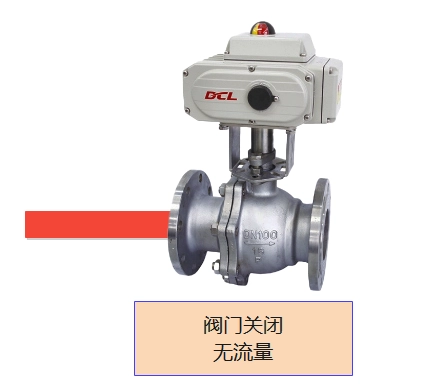
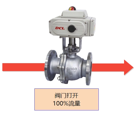
ON-OFF Electric Actuator Status
- Öffnen Sie – The valve is fully open, allowing fluid to pass through.
- Closed – The valve is fully closed, stopping fluid flow.
- In Transition – The valve is moving between open and closed positions.
- Fault/Error – The actuator has encountered an issue, such as power failure, overload, or obstruction.
Power by AC85-265V & Control by Relay
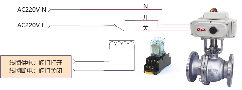
- When the L line is switched to the “off” input terminal via a relay, the actuator drives the valve to the closed position. Once the valve reaches the fully closed position, the actuator stops driving, and the electric valve remains closed.
- When the L line is switched to the “on” input terminal via a relay, the actuator drives the valve to the open position. Once the valve reaches the fully open position, the actuator stops driving, and the electric valve remains fully open.
- During the actuator’s operation, if the power supply on the AC220V L line is interrupted, the actuator stops driving, and the electric valve holds its current position.
- If the actuator is equipped with a heating dehumidifier, it is important to keep the AC220V L line powered after driving the actuator to the fully open or closed position.
Power by DC24V & Control by Relay
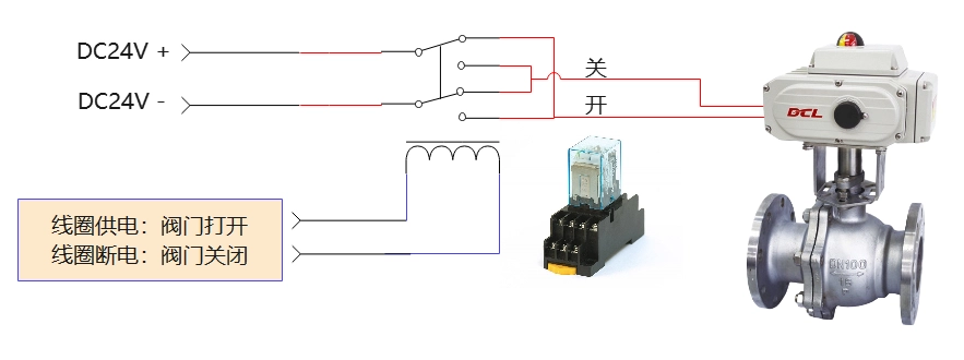
- When the relay switches the power + line to the “open” input terminal and the power – line to the “close” input terminal, the actuator drives the valve to the open position. Once the valve reaches the fully open position, the actuator stops driving, and the electric valve remains fully open.
- When the relay switches the power + line to the “close” input terminal and the power – line to the “open” input terminal, the actuator drives the valve to the closed position. Once the valve reaches the fully closed position, the actuator stops driving, and the electric valve remains fully closed.
- During the actuator’s operation, if the power supply is interrupted, the actuator stops driving, and the electric valve holds its current position.
- If the actuator is equipped with a heating dehumidifier, ensure that the power supply remains on after driving the actuator to the fully open or closed position.
Power by AC85-265V & Control by Switch
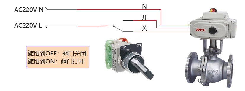
- When the L line is switched to the “close” input terminal via a mechanical switch, the actuator drives the valve to the closed position. Once the valve reaches the fully closed position, the actuator stops driving, and the electric valve remains fully closed.
- When the L line is switched to the “open” input terminal via a mechanical switch, the actuator drives the valve to the open position. Once the valve reaches the fully open position, the actuator stops driving, and the electric valve remains fully open.
- During the actuator’s operation, if the power supply on the AC220V L line is interrupted, the actuator stops driving, and the electric valve holds its current position.
- If the actuator is equipped with a heating dehumidifier, ensure that the AC220V L line remains powered after driving the actuator to the fully open or closed position.
Note: The circuit diagram above shows the basic functionality of the on/off actuator (electric valve). In practical applications, additional protective devices such as fuses and current limiters should also be considered.
Power by DC24V & Control by Switch
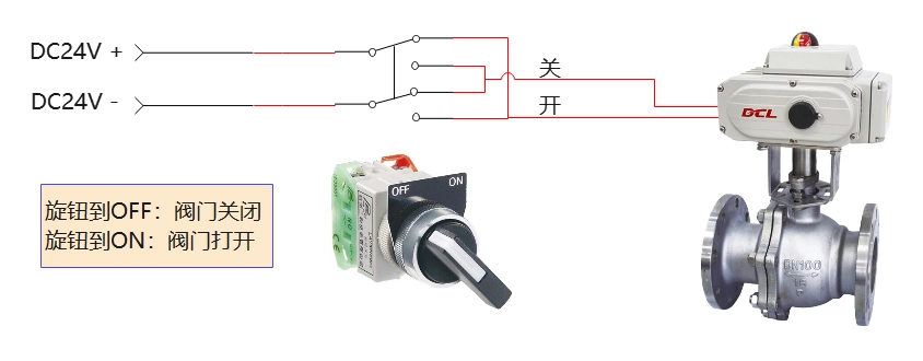
- When the mechanical switch connects the power + line to the “open” input terminal and the power – line to the “close” input terminal, the actuator drives the valve to the open position. Once the valve reaches the fully open position, the actuator stops driving, and the electric valve remains fully open.
- When the mechanical switch connects the power + line to the “close” input terminal and the power – line to the “open” input terminal, the actuator drives the valve to the closed position. Once the valve reaches the fully closed position, the actuator stops driving, and the electric valve remains fully closed.
- During the actuator’s operation, if the power supply is interrupted, the actuator stops driving, and the electric valve holds its current position.
- If the actuator is equipped with a heating dehumidifier, ensure that the power supply remains on after driving the actuator to the fully open or closed position.
Note: The circuit diagram above shows the basic functionality of the on/off actuator (electric valve). In practical applications, additional protective devices such as fuses and current limiters should also be considered.
Modulating Electric Actuator
When you install a DCL modulating electric actuator (valve) on the pipeline, you can control the valve’s position through 4-20mA or 0-10V analog signals, bus systems (such as Modbus, CAN, Profibus, DeviceNet, Foundation Fieldbus, HART, Ethernet), or IoT networks, enabling precise fluid flow regulation.
Modulating Electric Actuator Status
- Öffnen Sie – The valve is partially or fully open based on the control signal, allowing fluid flow.
- Closed – The valve is partially or fully closed based on the control signal, restricting or stopping fluid flow.
- In Transition – The valve is adjusting between open and closed positions according to the control signal.
- Error/Alarm – The actuator detects an issue such as a malfunction or communication failure, and the valve may stop or fail to reach the desired position.

Steuerung über 4-20mA
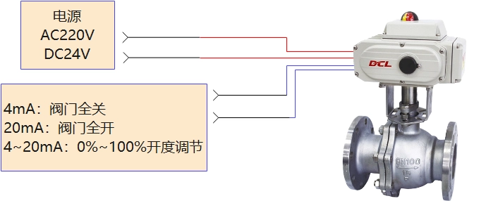
- The actuator adjusts the valve’s position according to a linear relationship with the 4-20mA input signal:
- 4mA corresponds to the valve being fully closed.
- 20mA corresponds to the valve being fully open.
- If the input signal falls outside the specified range, the actuator enters the loss of signal mode. Depending on the user’s settings, the actuator will drive the valve to:
- Fully open,
- Fully closed, or
- Maintain the valve’s position at the point where the signal was lost.
Note: The circuit diagram above shows the basic functionality of a modulating actuator (electric valve). In practical applications, additional protective devices such as fuses and current limiters should also be considered.
Steuerung über 2-10V
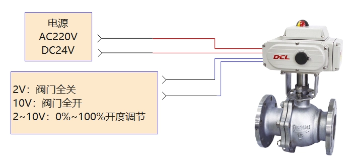
- The actuator adjusts the valve’s position based on a linear relationship with the 2-10V input signal:
- 2V corresponds to the valve being fully closed.
- 10V corresponds to the valve being fully open.
- If the input signal exceeds or falls outside the specified range, the actuator enters the loss of signal mode. Based on the user’s settings, the actuator will drive the valve to:
- Fully open,
- Fully closed, or
- Maintain the valve’s position where the signal was lost.
Note: The circuit diagram above illustrates the basic functionality of a modulating actuator (electric valve). In actual applications, additional protective devices such as fuses and current limiters should also be considered.
Steuerung über Feldbus
- Modbus, CAN, Profibus, DeviceNet, Foundation Fieldbus, HART, Ethernet
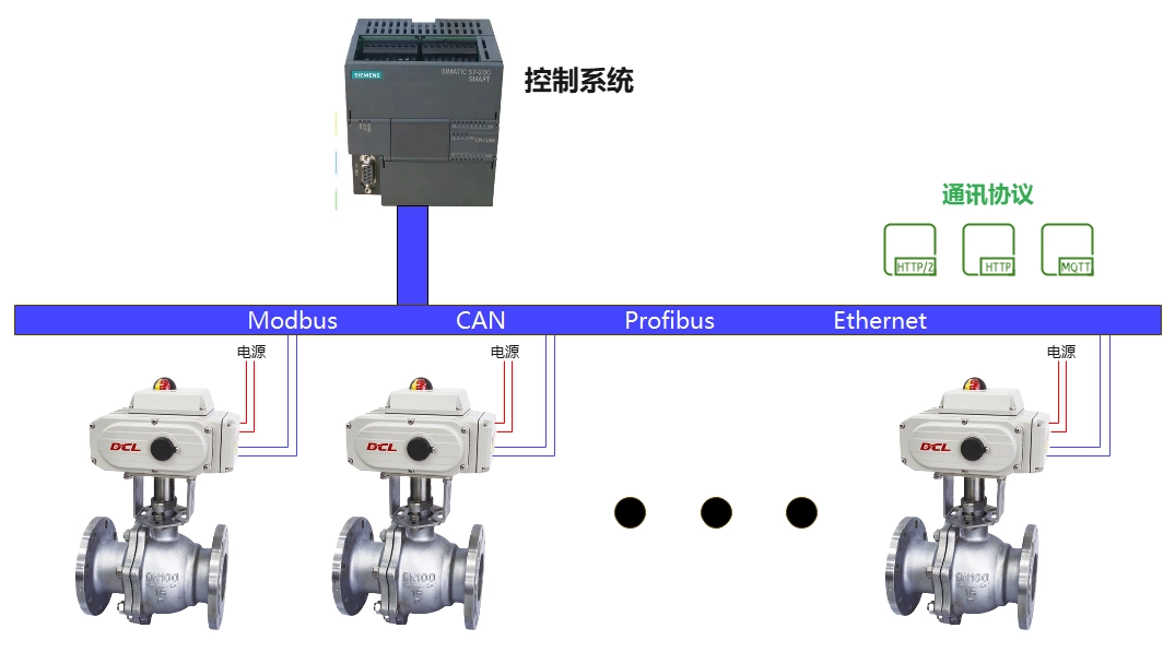
- The control system sends a position control command to the actuator via the bus communication protocol. The actuator then drives the valve to the specified position according to the bus command.
- If a bus error occurs, the actuator will drive the valve to one of the following positions based on user settings:
- Fully open,
- Fully closed, or
- Maintain the valve position at the time of the bus error.
- During the actuator’s operation, if the power supply is interrupted, the actuator stops driving, and the electric valve holds its current position.
Note: The circuit diagram above shows the basic functionality of a modulating actuator (electric valve). In practical applications, additional protective devices such as fuses and current limiters should also be considered.
Control via IIot
- NB-Iot, LoRA, LoRaWAN, 4G
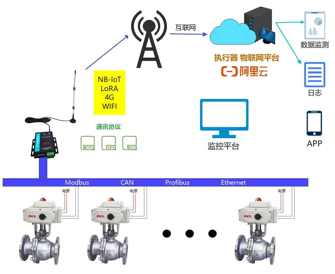
Through the actuator’s IoT platform, users can send position control commands to the actuator via a computer or smartphone app. Once the actuator receives the command from the IoT platform, it drives the valve to the specified position.
The IoT platform also allows for the monitoring and recording of critical factors such as actuator valve position, torque, power-on duration, adjustment frequency, etc., particularly in safety-critical or extreme application scenarios.
Additionally, you can perform fault diagnostics on actuators that are not equipped with IoT functionality. This application is highly effective for monitoring and troubleshooting occasional failures in actuator applications.
During the actuator’s operation, if the power supply is interrupted, the actuator stops driving, and the electric valve holds its current position.
Note: The circuit diagram above shows the basic functionality of a modulating actuator (electric valve). In practical applications, additional protective devices such as fuses and current limiters should also be considered.


 鄂公网安备 42018502006527号