




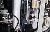



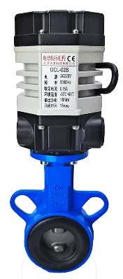
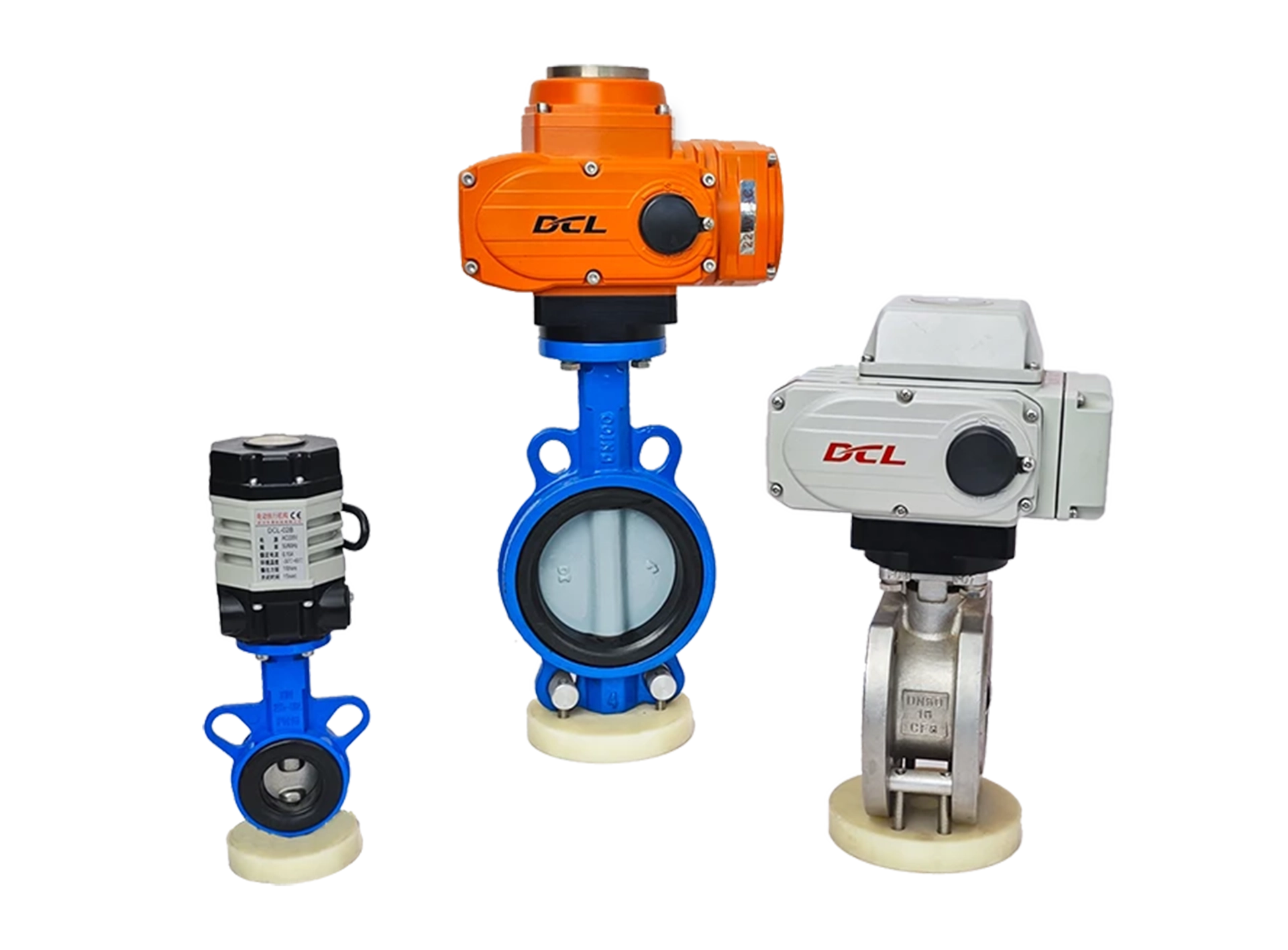
This guide is applicable to the DCL Ultra-Small Series actuators, with the following models:
DCL-02A
DCL-02B
DCL-02G
Распространенные неисправности и методы их устранения
| Неисправность | Возможные причины | Методы устранения неполадок |
|---|---|---|
| Actuator does not open or close on initial start | 1. Неправильная проводка | Check the wiring according to the actuator’s wiring diagram. |
| 2. Неправильный источник питания | Ensure the power supply voltage is within ±10% of the actuator’s rated voltage and the current is 3 times the rated current. | |
| 3. Faulty control switch or relay | Measure the input voltage at the actuator’s control terminal using a multimeter to verify it matches expectations. | |
| 4. Несоответствие системы управления | Test the actuator with a mechanical switch. If it operates normally, verify the control system’s output logic. | |
| 5. Multiple actuators or actuators and other devices connected in parallel | Switch actuators should use single-path control and not be wired in parallel, as this affects the startup capacitor. | |
| Исполнительный механизм может только открывать или закрывать. | 1. Неправильная проводка | Check the wiring using the actuator’s wiring diagram. |
| 2. Incorrect full open/close cam setting | Refer to the “How to Set Electric Switch-Type Valves” guide and correctly set the cam positions. | |
| Actuator stops in the middle of travel | 1. Valve jammed | Check for blockages in the valve. Clear any obstruction and retry after the actuator’s overload protection cools. |
| 2. Solid material in fluid causing valve jam | Inspect the fluid for solid particles causing valve jams. Clear the jam and retry after the actuator’s overload protection cools. | |
| 3. Incorrect full open/close stopper setting | Refer to the “How to Set Electric Switch-Type Valves” guide and correctly adjust the stopper positions. | |
| Unable to turn actuator using the handle | 1. Solid material in fluid causing valve to seize | Check for blockage in the valve. Clear the blockage and retry after the actuator’s overload protection cools. |
| 2. Valve seizing | Inspect the valve for jamming. Clear the blockage and retry after the actuator’s overload protection cools. | |
| 3. Damaged actuator reduction mechanism | Remove the actuator from the valve and rotate the handle. If it doesn’t move, replace the actuator. | |
| No position feedback signal | 1. Incorrect wiring at the switch | Check the wiring according to the actuator’s wiring diagram. |
| 2. Incorrect full open/close cam setting | Refer to the “How to Set Electric Switch-Type Valves” guide and set the cam position correctly. | |
| 3. Overcurrent causing position feedback switch damage | 1. Check if the full open/close cam is pressing on the position feedback switch correctly, as per the guide. | |
| 2. Measure if the position feedback circuit is closed. |
Verify that the operating conditions meet the parameter requirements.
Electric actuators may fail due to improper use or being used in incorrect operating conditions. When used within the operating conditions defined in the product specifications, the actuator can be expected to operate reliably for an extended period without failure.
Supply Voltage: The voltage from the power supply must be within the rated operating voltage range of the actuator. Overvoltage or undervoltage may shorten the actuator’s lifespan.
Supply Current: The starting current of the motor is significantly higher than the rated current. To ensure reliable operation, use a power supply capable of delivering at least 3 times the rated current of the actuator.
Температура: Ensure the actuator operates within its rated temperature range. Using the actuator outside this range may result in poor performance, reduced lifespan, and eventual failure.
Среда: The DCL switch-type actuator has an IP67 weatherproof rating, making it suitable for both indoor and outdoor applications. It offers a degree of protection against rain and splashing water, helping to prolong the actuator’s life by shielding it from rain, snow, ice, and UV (sunlight). However, in highly corrosive environments, electronic components may fail prematurely. Non-explosion-proof actuators should not be used in explosive environments.
Рабочий цикл: The DCL switch-type actuator has a duty cycle of 70% (42 seconds of operation per minute, followed by 18 seconds of rest). Exceeding this duty cycle may cause the motor to enter thermal protection.
Проверьте проводку привода.
Ensure the actuator is wired correctly according to the wiring diagram provided by the manufacturer. Follow these steps to verify the wiring:
Power Supply:
Check the power supply connections to ensure they match the actuator’s required input voltage and current.
Control Connections:
Verify that the input and output control connections are securely attached and in the correct configuration as per the actuator’s wiring diagram.
Signal Wiring:
Check the wiring for control signals, such as 4-20mA or 0-10V, depending on the actuator’s specifications.
Confirm that there are no loose connections or short circuits.
Grounding:
Ensure that the actuator is properly grounded to prevent electrical interference or damage.
Connections to Other Equipment:
If the actuator is connected to other devices, make sure those connections are also correct and do not cause interference or power issues.
If the wiring appears correct, but the actuator is still malfunctioning, further troubleshooting or assistance from a technician may be necessary.
A - С 2 активными выходами сигнала конечного положения
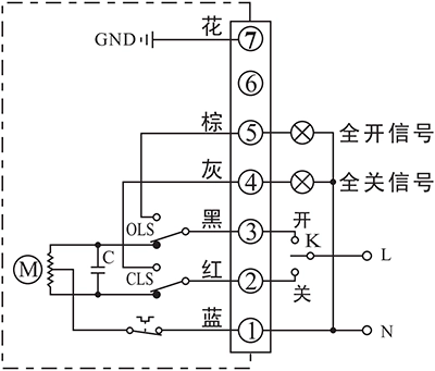
- Управление приводом для открытия или закрытия с помощью K
- Выходная клемма конечного положения ОТКРЫТЬ/ЗАКРЫТЬ будет передавать событие в виде активного сигнала 220 В переменного тока при достижении конечного положения.
Соединительные детали:
- Подключите нейтраль источника питания AC85-220 В к P1.
- Переключите линию AC85-220V на CLOSE(P2), чтобы закрыть клапан
- Переключите линию AC85-220V на OPEN (P3), чтобы открыть клапан.
- P5 - клемма конечного положения ОТКРЫТО, которая выводит источник AC220V, который может быть использован для управления индикаторной лампой, когда привод достиг конечного положения ОТКРЫТО.
- P6 - клемма конечного положения ОТКРЫТО, которая выводит источник AC220V, который может быть использован для управления индикаторной лампой, когда привод достиг конечного положения закрытия.
- Подключите заземление к P7.
B - С двумя пассивными концевыми выключателями
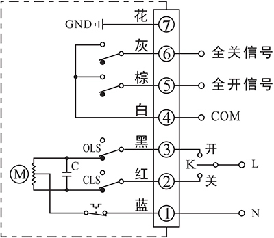
- Управление приводом для открытия или закрытия с помощью K
- Выходная клемма конечного положения ОТКРЫТЬ/ЗАКРЫТЬ посылает событие в виде пассивного сигнала при достижении конечного положения.
Соединительные детали:
- Подключите нейтраль источника питания AC85-220 В к P1.
- Переключите линию AC85-220V на CLOSE(P2), чтобы закрыть клапан
- Переключите линию AC85-220V на OPEN (P3), чтобы открыть клапан.
- P4 - это COM для пассивного контактного сигнала конечного положения ОТКРЫТЬ/ЗАКРЫТЬ, который обычно подключен к сигналу GND.
- P5 - клемма конечного положения ОТКРЫТО, которая будет подключена к COM, когда привод достигнет конечного положения ОТКРЫТО.
- P6 - клемма конечного положения ЗАКРЫТЬ, которая будет подключена к COM, когда привод достигнет конечного положения закрытия.
- Подключите заземление к P7.
G - двигатель постоянного тока с 2 переключателями конечного положения
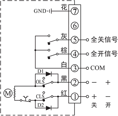
- Управление приводом для открытия или закрытия путем направления питания между клеммами 1 и 2
- Выходная клемма конечного положения ОТКРЫТЬ/ЗАКРЫТЬ посылает событие в виде пассивного сигнала при достижении конечного положения.
Соединительные детали:
- Подключите DC24V+ к P1 и DC24V- к P2, чтобы закрыть клапан.
- Подключите DC24V+ к P2 и DC24V- к P1, чтобы закрыть клапан.
- P3 - это COM для пассивного контактного сигнала конечного положения ОТКРЫТЬ/ЗАКРЫТЬ, который обычно подключен к сигналу GND.
- P4 - клемма конечного положения ОТКРЫТО, которая будет подключена к COM, когда привод достигнет конечного положения ОТКРЫТО.
- P5 - клемма конечного положения ЗАКРЫТЬ, которая будет подключена к COM, когда привод достигнет конечного положения закрытия.
- Подключите заземление к P7.
Примечание:
- Схема внутри пунктирной рамки - это внутренняя схема привода. В то время как схема снаружи - это демонстрация электрических соединений для использования привода.
- Если у вас есть другие специфические требования к соединительной цепи, пожалуйста, не стесняйтесь обращаться в нашу техническую поддержку.
When conducting troubleshooting on-site, feel free to contact our technical service personnel immediately for assistance in diagnosing and resolving the issue.
Contact phone number: 13026331611 (Mr. Chen)


 English (UK)
  香港中文
香港中文  繁體中文
繁體中文