








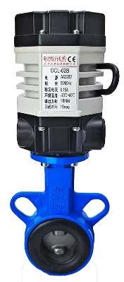
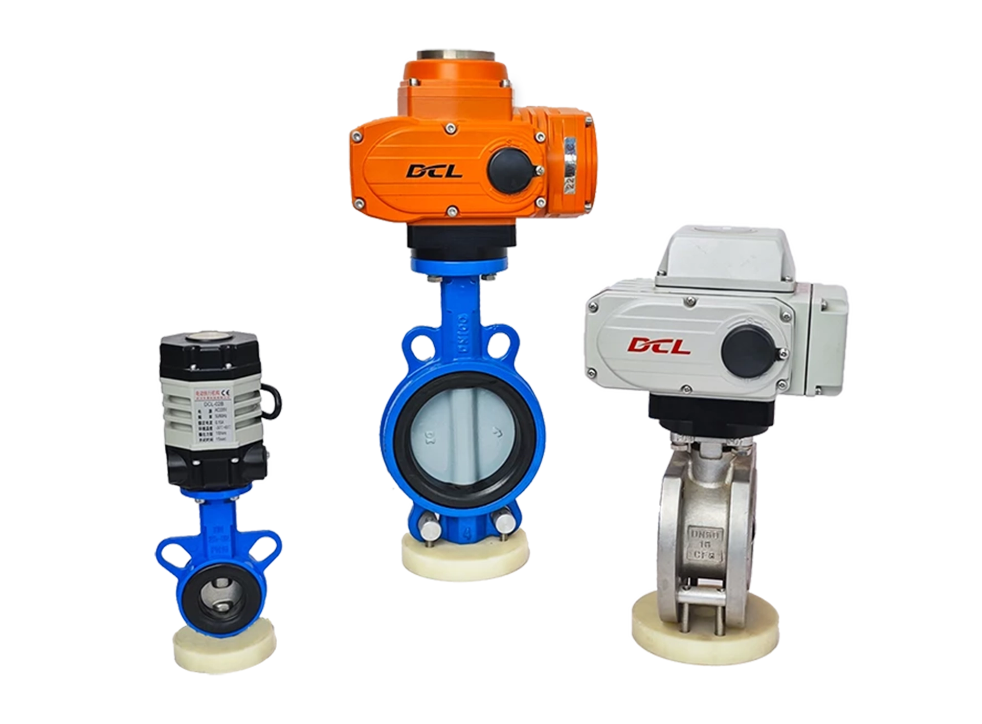
This guide is applicable to the DCL Ultra-Small Series actuators, with the following models:
DCL-02A
DCL-02B
DCL-02G
Guasti comuni e metodi di risoluzione dei problemi
| Colpa | Possible Causes | Troubleshooting Methods |
|---|---|---|
| Actuator does not open or close on initial start | 1. Cablaggio errato | Check the wiring according to the actuator’s wiring diagram. |
| 2. Alimentazione elettrica errata | Ensure the power supply voltage is within ±10% of the actuator’s rated voltage and the current is 3 times the rated current. | |
| 3. Faulty control switch or relay | Measure the input voltage at the actuator’s control terminal using a multimeter to verify it matches expectations. | |
| 4. Mancata corrispondenza del sistema di controllo | Test the actuator with a mechanical switch. If it operates normally, verify the control system’s output logic. | |
| 5. Multiple actuators or actuators and other devices connected in parallel | Switch actuators should use single-path control and not be wired in parallel, as this affects the startup capacitor. | |
| L'attuatore può solo aprire o chiudere | 1. Cablaggio errato | Check the wiring using the actuator’s wiring diagram. |
| 2. Incorrect full open/close cam setting | Refer to the “How to Set Electric Switch-Type Valves” guide and correctly set the cam positions. | |
| Actuator stops in the middle of travel | 1. Valve jammed | Check for blockages in the valve. Clear any obstruction and retry after the actuator’s overload protection cools. |
| 2. Solid material in fluid causing valve jam | Inspect the fluid for solid particles causing valve jams. Clear the jam and retry after the actuator’s overload protection cools. | |
| 3. Incorrect full open/close stopper setting | Refer to the “How to Set Electric Switch-Type Valves” guide and correctly adjust the stopper positions. | |
| Unable to turn actuator using the handle | 1. Solid material in fluid causing valve to seize | Check for blockage in the valve. Clear the blockage and retry after the actuator’s overload protection cools. |
| 2. Valve seizing | Inspect the valve for jamming. Clear the blockage and retry after the actuator’s overload protection cools. | |
| 3. Damaged actuator reduction mechanism | Remove the actuator from the valve and rotate the handle. If it doesn’t move, replace the actuator. | |
| No position feedback signal | 1. Incorrect wiring at the switch | Check the wiring according to the actuator’s wiring diagram. |
| 2. Incorrect full open/close cam setting | Refer to the “How to Set Electric Switch-Type Valves” guide and set the cam position correctly. | |
| 3. Overcurrent causing position feedback switch damage | 1. Check if the full open/close cam is pressing on the position feedback switch correctly, as per the guide. | |
| 2. Measure if the position feedback circuit is closed. |
Verify that the operating conditions meet the parameter requirements.
Electric actuators may fail due to improper use or being used in incorrect operating conditions. When used within the operating conditions defined in the product specifications, the actuator can be expected to operate reliably for an extended period without failure.
Supply Voltage: The voltage from the power supply must be within the rated operating voltage range of the actuator. Overvoltage or undervoltage may shorten the actuator’s lifespan.
Supply Current: The starting current of the motor is significantly higher than the rated current. To ensure reliable operation, use a power supply capable of delivering at least 3 times the rated current of the actuator.
Temperature: Ensure the actuator operates within its rated temperature range. Using the actuator outside this range may result in poor performance, reduced lifespan, and eventual failure.
Environment: The DCL switch-type actuator has an IP67 weatherproof rating, making it suitable for both indoor and outdoor applications. It offers a degree of protection against rain and splashing water, helping to prolong the actuator’s life by shielding it from rain, snow, ice, and UV (sunlight). However, in highly corrosive environments, electronic components may fail prematurely. Non-explosion-proof actuators should not be used in explosive environments.
Duty Cycle: The DCL switch-type actuator has a duty cycle of 70% (42 seconds of operation per minute, followed by 18 seconds of rest). Exceeding this duty cycle may cause the motor to enter thermal protection.
Verificare il cablaggio dell'attuatore
Ensure the actuator is wired correctly according to the wiring diagram provided by the manufacturer. Follow these steps to verify the wiring:
Power Supply:
Check the power supply connections to ensure they match the actuator’s required input voltage and current.
Control Connections:
Verify that the input and output control connections are securely attached and in the correct configuration as per the actuator’s wiring diagram.
Signal Wiring:
Check the wiring for control signals, such as 4-20mA or 0-10V, depending on the actuator’s specifications.
Confirm that there are no loose connections or short circuits.
Grounding:
Ensure that the actuator is properly grounded to prevent electrical interference or damage.
Connections to Other Equipment:
If the actuator is connected to other devices, make sure those connections are also correct and do not cause interference or power issues.
If the wiring appears correct, but the actuator is still malfunctioning, further troubleshooting or assistance from a technician may be necessary.
A - Con 2 uscite di segnale di posizione finale attive
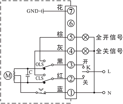
- Attuatore di controllo per aprire o chiudere con K
- Il terminale di uscita della posizione finale APERTURA/CHIUSURA invierà un segnale attivo a 220 V CA quando la posizione finale viene raggiunta.
Dettagli di connessione:
- Collegare il neutro dell'alimentazione CA 85-220V a P1.
- Portare la linea AC85-220V su CHIUSO (P2) per chiudere la valvola
- Portare la linea AC85-220V su OPEN (P3) per aprire la valvola.
- P5 è il terminale di fine corsa APERTO che emette una sorgente di corrente alternata a 220 V utilizzabile per azionare una spia luminosa quando l'attuatore raggiunge la posizione di fine corsa.
- P6 è il terminale di fine corsa APERTO che emette una sorgente di corrente alternata a 220 V utilizzabile per azionare una spia luminosa quando l'attuatore raggiunge la posizione di fine corsa di chiusura.
- Collegare la terra al pin P7.
B - With 2 passive end-position switche
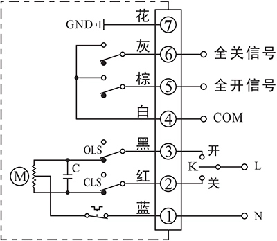
- Attuatore di controllo per aprire o chiudere con K
- Il terminale di uscita della posizione finale OPEN/CLOSE invierà un segnale passivo quando la posizione finale viene raggiunta.
Dettagli di connessione:
- Collegare il neutro dell'alimentazione CA 85-220V a P1.
- Portare la linea AC85-220V su CHIUSO (P2) per chiudere la valvola
- Portare la linea AC85-220V su OPEN (P3) per aprire la valvola.
- P4 è il terminale COM per il segnale di contatto passivo di posizione finale APERTO/CHIUSO, che normalmente è collegato al segnale GND.
- P5 è il terminale di fine corsa APERTO che verrà collegato a COM quando l'attuatore raggiungerà la posizione di fine corsa aperta.
- P6 è il terminale di CHIUSURA finale che verrà collegato a COM quando l'attuatore raggiungerà la posizione finale di chiusura.
- Collegare la terra al pin P7.
G - Motore CC con 2 interruttori di fine corsa
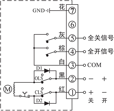
- Attuatore di controllo per aprire o chiudere in base alla direzione dell'alimentazione tra i terminali 1 e 2
- Il terminale di uscita della posizione finale OPEN/CLOSE invierà un segnale passivo quando la posizione finale viene raggiunta.
Dettagli di connessione:
- Collegare il polo positivo DC24V+ al pin P1 e il polo negativo DC24V- al pin P2 per chiudere la valvola.
- Collegare il polo positivo DC24V+ al pin P2 e il polo negativo DC24V- al pin P1 per chiudere la valvola.
- P3 è il terminale COM per il segnale di contatto passivo di posizione finale APERTO/CHIUSO, che normalmente è collegato al segnale GND.
- P4 è il terminale di fine corsa APERTO che verrà collegato a COM quando l'attuatore raggiungerà la posizione di fine corsa aperta.
- P5 è il terminale di CHIUSURA finale che verrà collegato a COM quando l'attuatore raggiungerà la posizione finale di chiusura.
- Collegare la terra al pin P7.
Nota:
- Il circuito all'interno del riquadro tratteggiato è il circuito interno dell'attuatore. Il circuito esterno, invece, mostra lo schema di collegamento elettrico per il funzionamento dell'attuatore.
- Se avete altre esigenze specifiche riguardo al circuito di collegamento, non esitate a contattare il nostro supporto tecnico.
When conducting troubleshooting on-site, feel free to contact our technical service personnel immediately for assistance in diagnosing and resolving the issue.
Contact phone number: 13026331611 (Mr. Chen)


 English (UK)
  香港中文
香港中文  繁體中文
繁體中文  English (Canada)
  English (South Africa)
  English (Australia)
  English (New Zealand)
  English
  Español de Puerto Rico
  Français du Canada
  Español de México
  Español de Chile
  Español de Colombia
  Español de Uruguay
  עִבְרִית
  Nederlands (België)
  Français de Belgique
  Eesti
Eesti  Latviešu valoda
  Lietuvių kalba
  Français
  Deutsch
  Norsk nynorsk
  Deutsch (Österreich)
  Slovenčina
  Deutsch (Schweiz)
  Italiano