







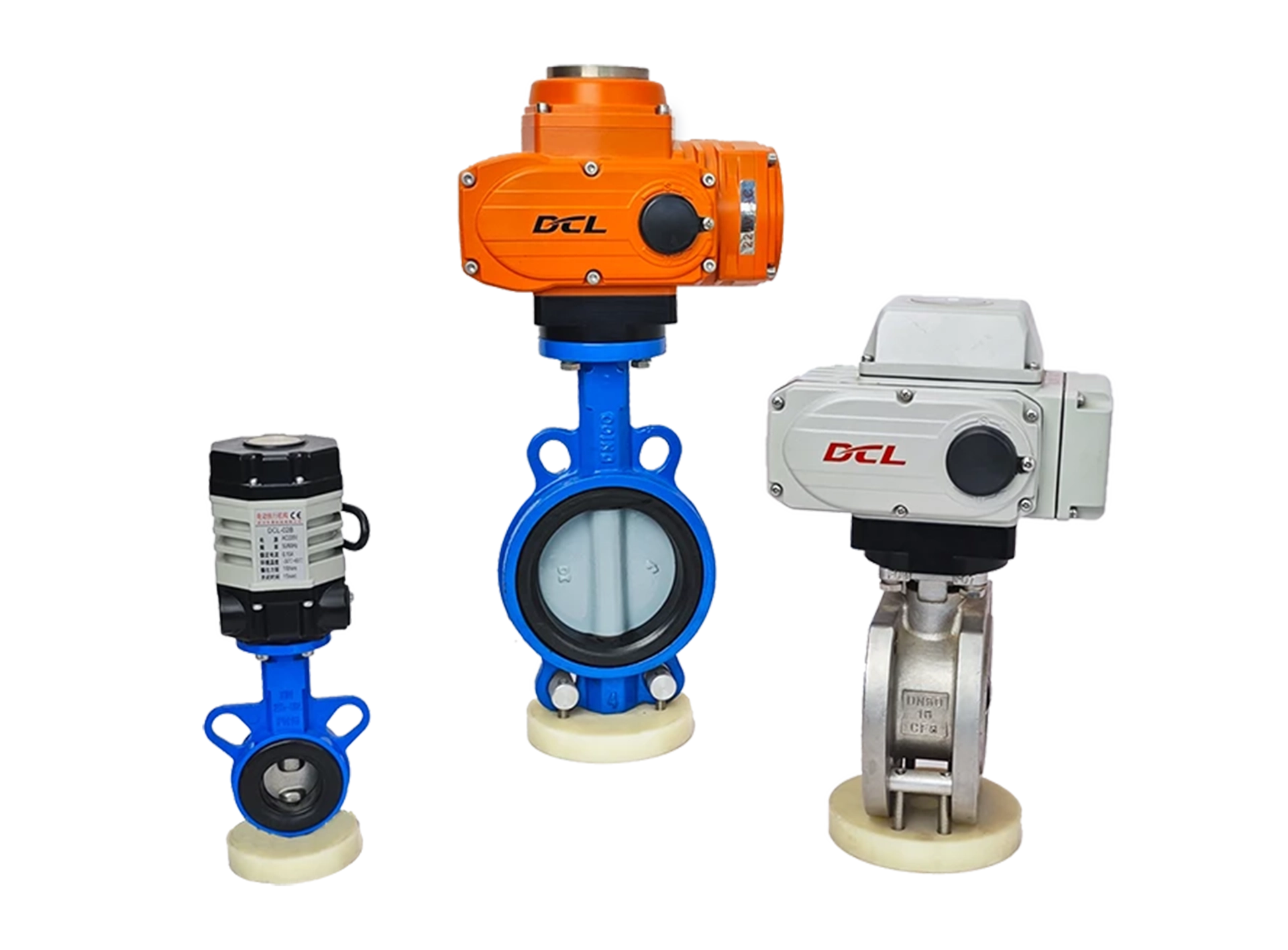
Ultra Small Actuator
DCL-02
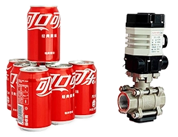
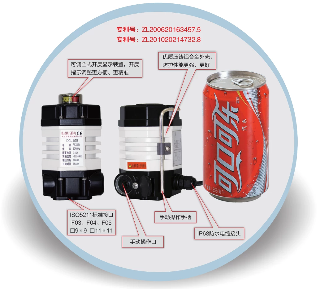
- Small size same as a cola can
- High-strength aluminum alloy shell for strong protection.
- High EMI performance.
Movement Direction
Part-turn
Damper
0 - 270°
Coppia/Tempo di funzionamento
9~18Nm
7~60S
Tipo di incarico
Modulazione
On - Off
Tensione di alimentazione
24 V CC
110 V CA
220 V CA
Input/Output Signal
4 - 20mA
0 - 10V
IO Interface
Opzioni aggiuntive
Deumidificazione
Tipo di incarico
Modulazione
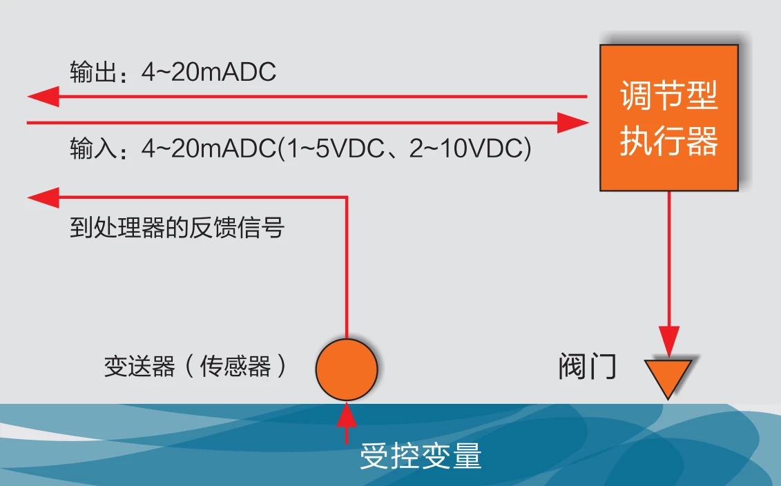
The actuator read the target position value from control system through 4-20mA, 2-10V or field bus such as modbus, ethernet and etc.
Then actuator drive the valve to the target position with interior control algorithm.
The actuator will always output the real-time valve position through 4-20mA, 2-10V or field bus.
Operated in type of duty S4, the actuator can starts 1200 times per hour.
On - Off
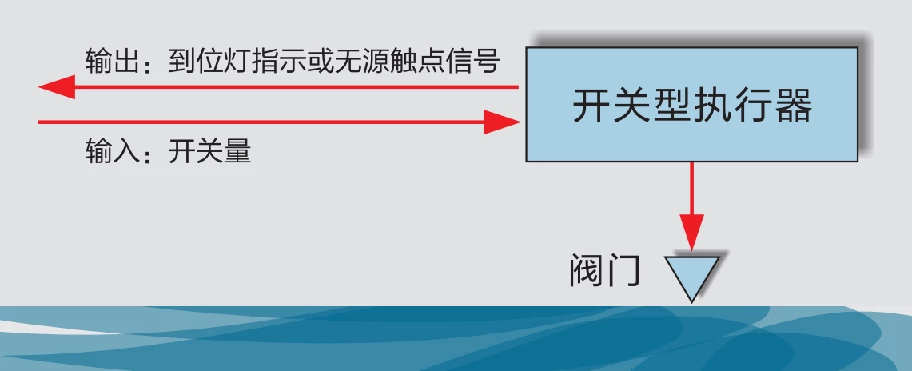
The actuator read the open or close requirement from control system through IO interface such as passive signal or 24VDC/220VAC active signal.
Then actuator drive the valve to the end-position of OPEN or CLOSE as input signal required.
The actuator will output a feedback signal of OPEN or CLOSE when end-position been reached.
Operated in type of duty S2, the actuator can drive valve continuously for 15 minutes.
Features
Motor with Over Temperature Protection
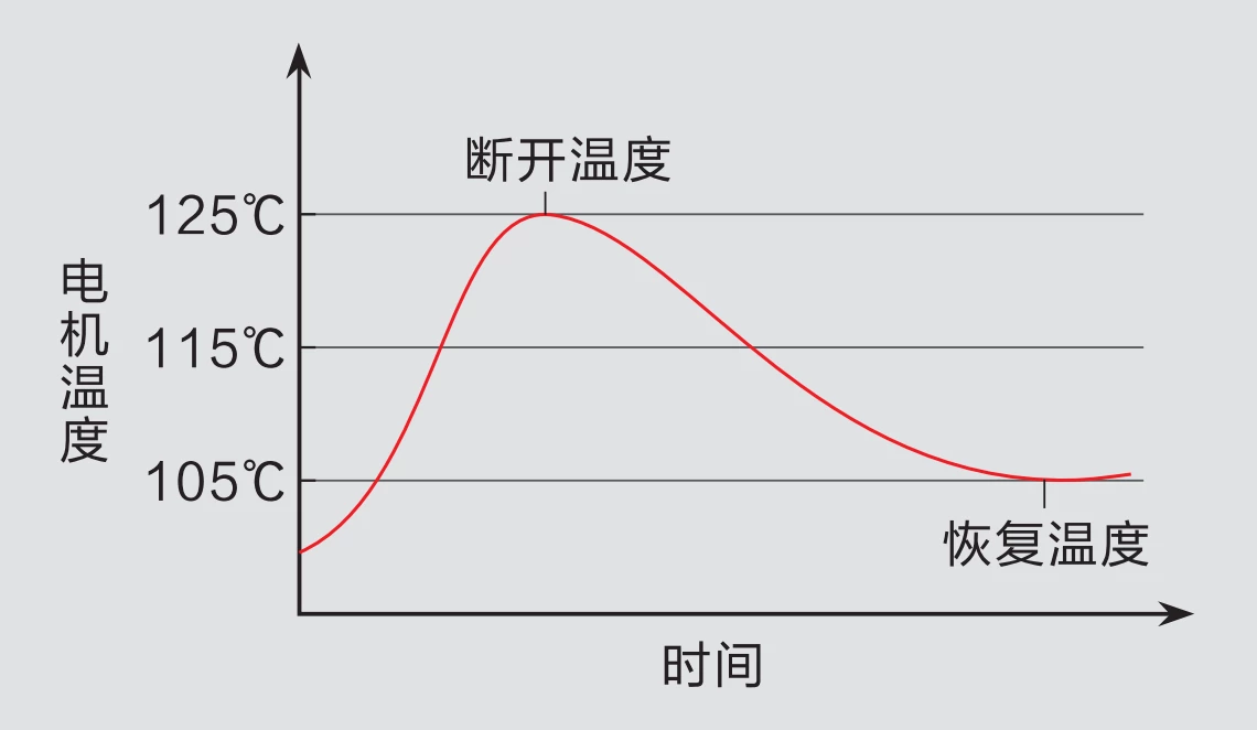
DCL specially design the motor to fit the actuator requirement so that the motor in DCL actuator can supply a high start torque while maintain a high efficiency in the start phase to make the temperature rise as low as possible. In the meantime the motor have a small moment of inertia to make sure the high precision in modulation.
There is an over temperature protection device mounted in the motor which will cut the power supply when the motor temperature goes higher then the limited temperature(105℃/85℃ can be selected up on the application scenario) and connect the power supply again when the temperature recovered below the Normal temperature.
Dual Position Limiter
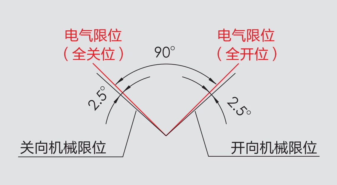
There are 2 position limit devices to protect valve from damage by operation over swing angle.
Electric limit switch are mounted on the both end-position of OPEN and CLOSE. So the power supply to motor will be cut off to stop driving the valve after limited end-position was reached.
Also there are 2 mechanical limiters mounted on the output shaft to protect the valve from swing over stroke range. The mechanical limiter will not take effect in normal operation cause the electric limit switch is ahead of the mechanical limiter and will be triggered before the output shaft can reach the mechanical limited positon.
Technical Parameters
| Power Supply | DC24V, AC24V, AC110V, AC220V |
| Standard Torque/Time | 18Nm/15S |
| Optional Torque/Time | 9Nm/7S, 18Nm/60S |
| Rotation Angle Range | 0~90° |
| Motor Power/Current | DC24V:8W / 0.7A AC24V:6W / 1.3A AC110V: 6W / 0.3A AC220V:6W / 0.15A |
| Control Circuit | DC24V: E-type/G-type |
| Weight | 1.2kg |
| Insulation Resistance | DC24V/AC24V:100MΩ/250VDC AC110V/AC220V:100MΩ/500VDC |
| Withstand Voltage | DC24V/AC24V: 500VAC for 1 minute |
| Water Proof Level | IP67 |
| Installation orientation | 360 ° installation at any angle |
| Electrical Interface | 7-core cable connection |
| Working Temperature | -25℃ ~ +55℃ |
| Selection of fuses | DC24V:2A AC24V:3A AC110V/AC220V:1A |
| DCL-02 Adjustable Control Parameters | |
| Segnale di ingresso | 4~20mA, 0~10V arbitrary calibration |
| output Signal | 4~20mA, 0~10V arbitrary calibration |
| Bus | 485/Modbus/CAN |
| Internet of Things | WIFI/LoRA/4G |
| Basic Error | ≤±1% |
| Check back | ≤1% |
| Hysteresis | Adaptive Hysteresis, customized |
| Reposition Times | 0 times |
| Repeatability Error | ≤1% |
Dimensions
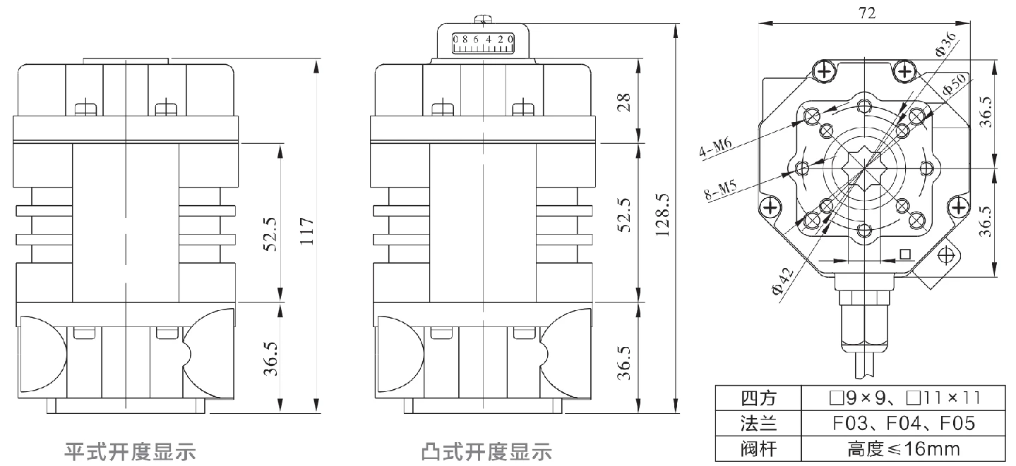
Application Circuit
Modulazione
E - Modulazione con un'unità di controllo
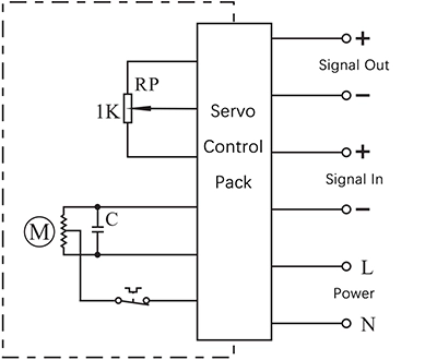
- Ingresso: 4~20mA / 0~10V
- Uscita: 4~20mA / 0~10V
Dettagli di connessione:
- Collegare la linea di alimentazione CA 85-220V al terminale L e il neutro al terminale N.
- Collegamento della sorgente di segnale di ingresso 4-20mA/2-10V dal sistema di controllo all'ingresso-/+.
- Collegare l'uscita +/- al sistema per inviare la posizione della valvola in tempo reale.
On - Off
A - With 2 active end-position signal outputs
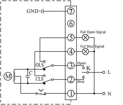
- Control actuator to open or close with K
- The output terminal of end-position OPEN/CLOSE will send out the event as a 220VAC active signal form when the end-position was reached.
Dettagli di connessione:
- Connecting AC85-220V supply power neutral to P1.
- Switch AC85-220V line to CLOSE(P2) to close the valve
- Switch AC85-220V line to OPEN(P3) to open the valve.
- P5 is end-position OPEN terminal which will output a AC220V source which can be used to drive an Indication light when actuator reached end-position of open.
- P6 is end-position OPEN terminal which will output a AC220V source which can be used to drive an Indication light when actuator reached end-position of close.
- Connect earth to P7.
B - With 2 passive end-position switche
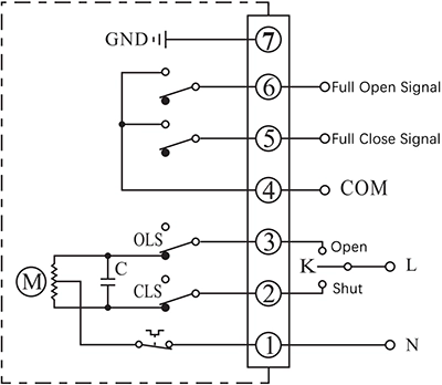
- Control actuator to open or close with K
- The output terminal of end-position OPEN/CLOSE will send out the event as a passive signal form when the end-position was reached.
Dettagli di connessione:
- Connecting AC85-220V supply power neutral to P1.
- Switch AC85-220V line to CLOSE(P2) to close the valve
- Switch AC85-220V line to OPEN(P3) to open the valve.
- P4 is the COM for passive contact signal of end-position OPEN/CLOSE which is normally connected to signal GND.
- P5 is end-position OPEN terminal which will be connected to COM when actuator reached end-position of open.
- P6 is end-position CLOSE terminal which will be connected to COM when actuator reached end-position of close.
- Connect earth to P7.
G - DC motor with 2 end-position switches
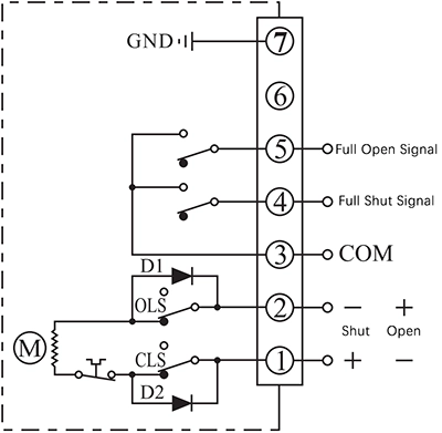
- Control actuator to open or close by the supply power direction between the terminal 1 and 2
- The output terminal of end-position OPEN/CLOSE will send out the event as a passive signal form when the end-position was reached.
Dettagli di connessione:
- Connecting DC24V+ to P1 and DC24V- to P2 to close the valve.
- Connecting DC24V+ to P2 and DC24V- to P1 to close the valve.
- P3 is the COM for passive contact signal of end-position OPEN/CLOSE which is normally connected to signal GND.
- P4 is end-position OPEN terminal which will be connected to COM when actuator reached end-position of open.
- P5 is end-position CLOSE terminal which will be connected to COM when actuator reached end-position of close.
- Connect earth to P7.
Nota:
- Il circuito all'interno del riquadro tratteggiato è il circuito interno dell'attuatore. Il circuito esterno, invece, mostra lo schema di collegamento elettrico per il funzionamento dell'attuatore.
- Se avete altre esigenze specifiche riguardo al circuito di collegamento, non esitate a contattare il nostro supporto tecnico.


 English (UK)
  香港中文
香港中文  繁體中文
繁體中文  English (Canada)
  English (South Africa)
  English (Australia)
  English (New Zealand)
  English
  Español de Puerto Rico
  Français du Canada
  Español de México
  Español de Chile
  Español de Colombia
  Español de Uruguay
  עִבְרִית
  Nederlands (België)
  Français de Belgique
  Eesti
Eesti  Latviešu valoda
  Lietuvių kalba
  Français
  Deutsch
  Norsk nynorsk
  Deutsch (Österreich)
  Slovenčina
  Deutsch (Schweiz)
  Italiano