


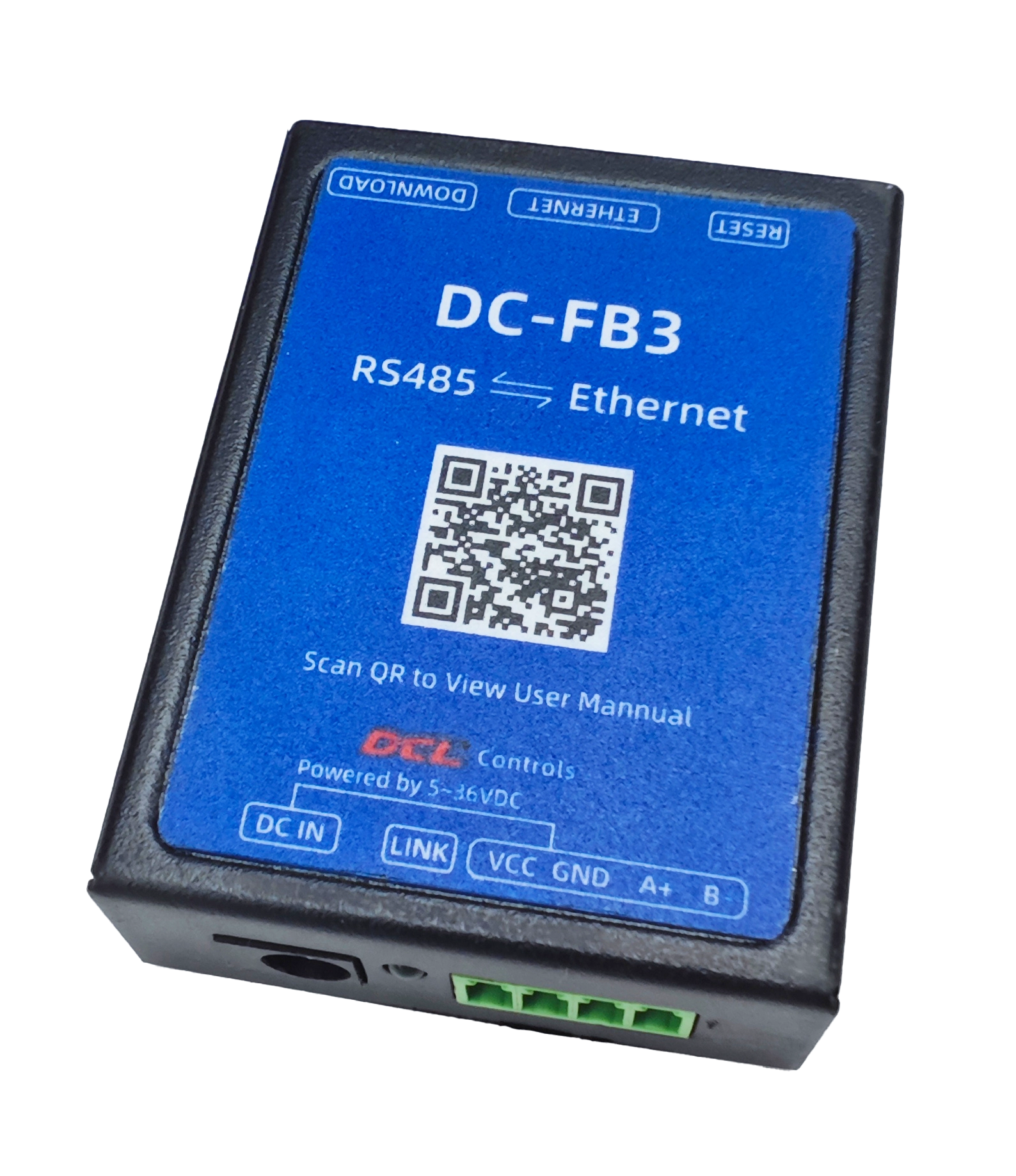
The DC-FB3 module, when installed in the DCL electric actuator, allows for controlling the valve’s position using Modbus-TCP/IP. The installation is shown below:
1. Controlling DCL Electric Actuator via Modbus-TCP/IP Using Default Parameters
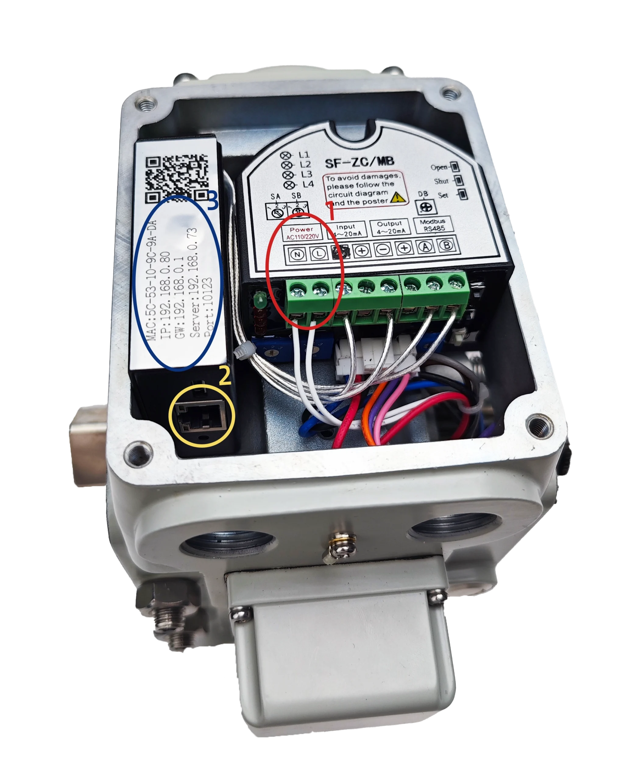
The DC-FB3 is pre-configured in Client mode. Using the default MAC, IP, Gateway, Server, and Port parameters, you can control the DCL electric actuator via Modbus-TCP/IP. The default parameters are indicated within the blue box in the image below.
When using the default parameters, you can skip step 2 and proceed directly to step 3, using Modbus-TCP/IP to control the DCL electric actuator.
2. Changing TCP/IP Network Parameters
2.1 Connect DC-FB3 to PC Using DC-FB1 (USB to RS485)
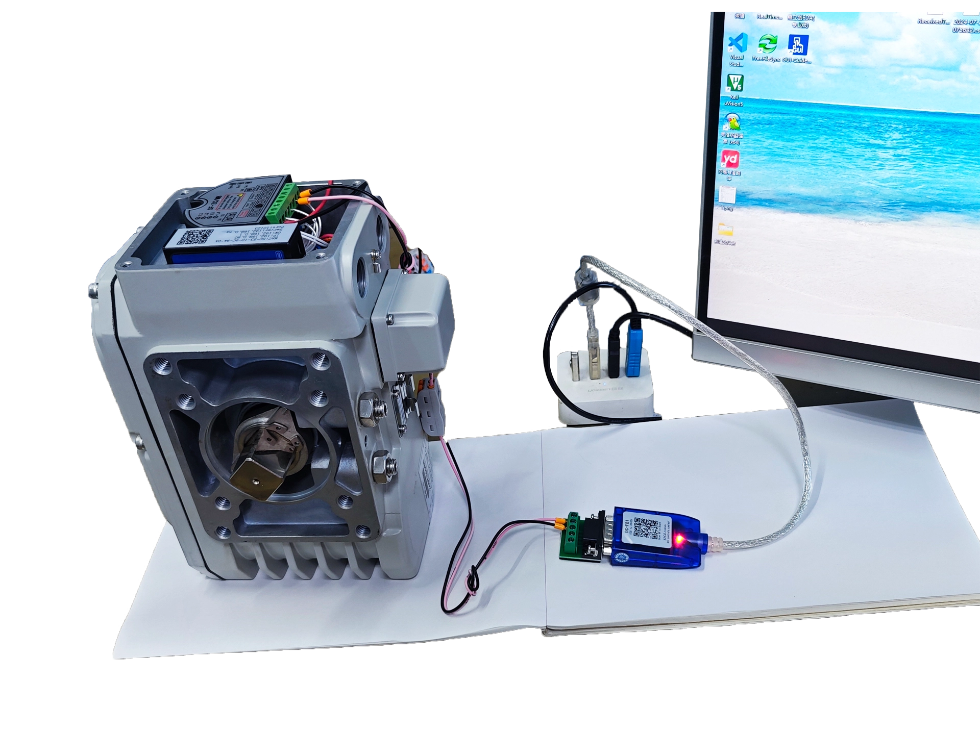
The wiring for connecting the DC-FB3 is as follows:
Red Box 1: Connect to AC220V power supply.
Green Box 4: Connect to the RS485 interface (A/B) of DC-FB1.
DC-FB1 USB: Plug into the PC.
For further details, refer to the DC-FB1 user manual.
2.2 Use Configuration Software on PC to Set Network Parameters
Download Configuration Software: Install the necessary configuration software for setting the network parameters.
Select Correct Port: Open the configuration software, choose the correct port, and click CONNECT to connect to DC-FB3.
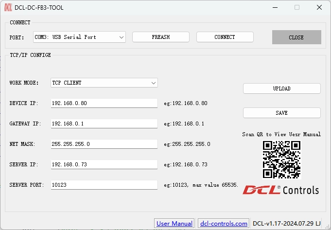
Once connected, the configuration software will automatically read the parameters from the DC-FB3.
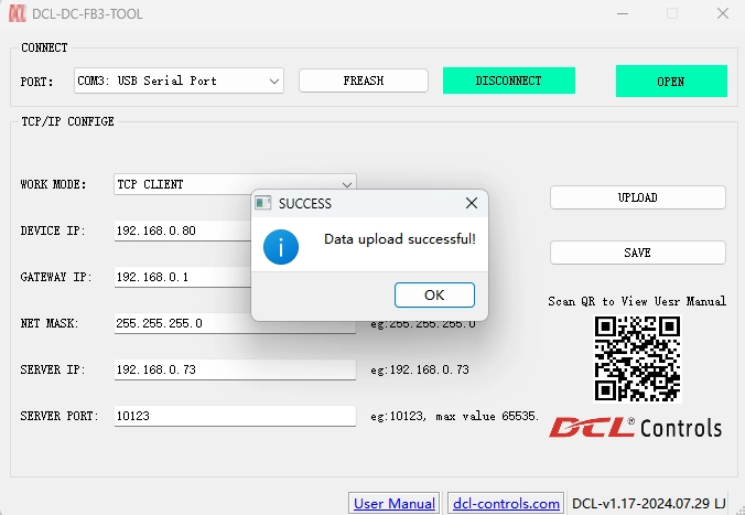
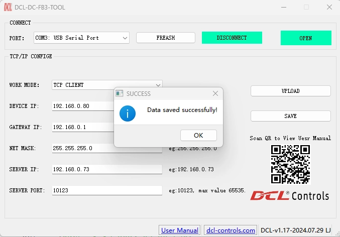
Change Network Parameters: After modifying the network parameters, click SAVE to store the updated parameters in the DC-FB3.
3. Control DCL Actuator through Modbus-TCP/IP
Hardware connections
- Connect AC220V power supply to terminals marked with red box 1
- Insert RJ45 plug into socket marked with yellow box 2
Now you can control actuator through modbus-RTU commands following the DCL Actuator Modbus Application Manual


 鄂公网安备 42018502006527号