




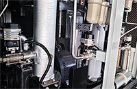



This guide applies to the switch-type actuators of the DCL explosion-proof series, standard series, and quick-open series. The models are as follows:
Weather-proof Actuator: DCL-05, DCL-10, DCL-20, DCL-40, DCL-60, DCL-100, DCL-160, DCL-250
Explosion-Proof Actuator: DCL-Ex05, DCL-Ex10, DCL-Ex20, DCL-Ex40, DCL-Ex60
Quick-Turn Actuator: DCL-K05, DCL-K10, DCL-K20, DCL-K40, DCL-K100
Common Faults and Troubleshooting Methods
| Fault | Possible Causes | Troubleshooting Methods |
|---|---|---|
| Actuator does not open or close at startup | 1. Incorrect wiring. 2. Incorrect power supply. 3. Faulty control switch or relay. 4. Control system mismatch. 5. Multiple actuators or actuator in parallel with other devices. | 1. Check the wiring against the actuator’s wiring diagram to ensure it is correct. 2. Verify power supply output voltage is ±10% of rated voltage, and the current is at least three times the actuator’s rated current. 3. Use a multimeter to measure input voltage at the actuator’s control terminal and confirm it matches expected values. 4. Use a mechanical switch to test actuator operation. If it works, verify the control system output logic. 5. Switch-type actuators should not be connected in parallel with other devices; use a single control circuit. |
| Actuator only opens or closes, not both | 1. Incorrect wiring. 2. Incorrect full open/full close cam settings. | 1. Use a mechanical switch to test actuator functionality. If it works, verify the control system output logic. 2. Check actuator’s wiring against the wiring diagram. 3. Adjust the cam settings according to the “How to Set Switch-type Electric Valves” manual. |
| Actuator stops in the middle of its stroke | 1. Valve is stuck. 2. Solid particles in the fluid medium causing valve blockage. 3. Incorrect full open/full close block settings. | 1. Check if the valve is stuck. Remove obstructions and retry after the actuator cools down from overload protection. 2. Inspect the fluid medium for solid particles. Remove any blockage and retry after cooling. 3. Adjust block settings according to the “How to Set Switch-type Electric Valves” manual. |
| Cannot turn the actuator with the handwheel | 1. Solid particles in the fluid medium causing valve blockage. 2. Valve is stuck. 3. Actuator’s reduction mechanism is damaged. | 1. Check fluid medium for particles causing blockage. Remove obstructions and retry after cooling. 2. Inspect valve for any stuck parts. Remove blockage and retry. 3. If actuator cannot be turned by hand, remove it from the valve. If it still doesn’t turn, replace with a new actuator. |
| No output from position feedback signal | 1. Incorrect switch wiring. 2. Incorrect full open/full close cam settings. 3. Overcurrent causing damage to the position feedback signal switch. | 1. Check wiring of the switch against the actuator’s wiring diagram to ensure it is correct. 2. Verify full open/full close cam is properly compressing the position feedback switch. 3. Measure the position feedback circuit to check if the switch is intact and properly connected. |
Please check if the operating conditions meet the parameter requirements.
Electric actuators may fail due to improper use or operating in incorrect conditions. To ensure long-term, trouble-free operation, the actuator must be used within the operating conditions specified in the product datasheet.
Power Supply Voltage: The supply voltage must be within the actuator’s rated operating voltage range. Overvoltage or undervoltage may reduce the actuator’s lifespan.
Power Supply Current: Since the motor’s starting current is significantly higher than the rated current, please ensure that the power supply can provide a current capacity at least 3 times the actuator’s rated current to ensure reliable operation.
Temperature: Ensure that the actuator operates within the rated temperature range. Operating the actuator outside the specified temperature range may cause malfunction, reduced lifespan, or eventual failure.
Environment: The DCL switch-type actuators are rated at IP67 for wind and rain protection. They are generally suitable for both indoor and outdoor use, providing protection against rain, splashes, and UV exposure (sunlight), which typically extends the product’s lifespan. Extremely corrosive environments may cause premature failure of electronic components. Do not use non-explosion-proof actuators in explosive atmospheres.
Duty Cycle: The duty cycle of the DCL switch-type actuator is 70% (42 seconds of operation per minute, with a required 18 seconds off). Exceeding a 70% duty cycle will trigger thermal protection for the motor.
Check if the wiring of the actuator is correct.
Ensure that all electrical connections are properly made according to the wiring diagram provided in the product manual. Incorrect wiring can lead to malfunction or damage to the actuator. Verify the following:
The power supply connections are properly secured and there are no loose wires.
The control signal wiring is correctly connected, ensuring polarity and signal type are properly matched.
The ground connection (if applicable) is properly established to avoid electrical hazards.
Double-check the connection of any external components, such as limit switches or feedback devices, to ensure they are wired correctly.
ĮJUNGTA - IŠJUNGTA
A - Su 2 aktyviais galinės padėties signalo išėjimais
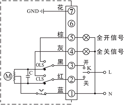
- Valdykite pavarą atidarymui arba uždarymui su K
- Galinės padėties ATIDARYTA/UŽDARYTA išvesties gnybtas išsiųs įvykį 220 V kintamosios srovės aktyvaus signalo forma, kai bus pasiekta galinė padėtis.
Connecting Details:
- Connecting AC85-220V supply power neutral to P1.
- Switch AC85-220V line to CLOSE(P2) to close the valve
- Switch AC85-220V line to OPEN(P3) to open the valve.
- P5 is end-position OPEN terminal which will output a AC220V source which can be used to drive an Indication light when actuator reached end-position of open.
- P6 is end-position OPEN terminal which will output a AC220V source which can be used to drive an Indication light when actuator reached end-position of close.
- Connect earth to P7.
B - Su 2 pasyviais galinės padėties jungikliais
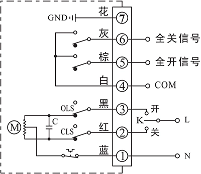
- Valdykite pavarą atidarymui arba uždarymui su K
- Galinės padėties ATIDARYTA/UŽDARYTA išvesties gnybtas pasiųs įvykį pasyvaus signalo pavidalu, kai bus pasiekta galinė padėtis.
Connecting Details:
- Connecting AC85-220V supply power neutral to P1.
- Switch AC85-220V line to CLOSE(P2) to close the valve
- Switch AC85-220V line to OPEN(P3) to open the valve.
- P4 is the COM for passive contact signal of end-position OPEN/CLOSE which is normally connected to signal GND.
- P5 is end-position OPEN terminal which will be connected to COM when actuator reached end-position of open.
- P6 is end-position CLOSE terminal which will be connected to COM when actuator reached end-position of close.
- Connect earth to P7.
G - Nuolatinės srovės variklis su 2 galinės padėties jungikliais

- Valdykite pavarą, kad ji atidarytų arba uždarytų maitinimo kryptį tarp 1 ir 2 gnybtų
- Galinės padėties ATIDARYTA/UŽDARYTA išvesties gnybtas pasiųs įvykį pasyvaus signalo pavidalu, kai bus pasiekta galinė padėtis.
Connecting Details:
- Connecting DC24V+ to P1 and DC24V- to P2 to close the valve.
- Connecting DC24V+ to P2 and DC24V- to P1 to close the valve.
- P3 is the COM for passive contact signal of end-position OPEN/CLOSE which is normally connected to signal GND.
- P4 is end-position OPEN terminal which will be connected to COM when actuator reached end-position of open.
- P5 is end-position CLOSE terminal which will be connected to COM when actuator reached end-position of close.
- Connect earth to P7.
H - 3 fazių 380 V kintamosios srovės variklis su 2 galinės padėties jungikliais
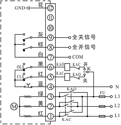
- Išorinio keitiklio valdomas pavaros atidarymo arba uždarymo valdymas, siekiant pakeisti maitinimo fazę.
- Galinės padėties ATIDARYTA/UŽDARYTA išvesties gnybtas pasiųs įvykį pasyvaus signalo pavidalu, kai bus pasiekta galinė padėtis.
Connecting Details:
- Connecting a 3 phase AC380V inverter output to P1, P2 and P3, then the actuator can be controlled to open or close the valve by change the 3 phase order.
- Connecting AC380V neutral to N(P4).
- P5 is used for cooperating with an external switch to control the inverter 3 phase order. This terminal is connected to N(P4) when actuator is not in end-position of CLOSE and disconnected from N(P4) after actuator reached end-position of CLOSE.
- P6 is used for cooperating with an external switch to control the inverter 3 phase order. This terminal is connected to N(P4) when actuator is not in end-position of OPEN and disconnected from N(P4) after actuator reached end-position of OPEN.
- P7 is the COM for passive contact signal of end-position OPEN/CLOSE which is normally connected to signal GND.
- P8 is end-position OPEN terminal which will be connected to COM when actuator reached end-position of open.
- P9 is end-position CLOSE terminal which will be connected to COM when actuator reached end-position of close.
- Connect earth to P12.
Poslinkis ir pozicionavimas
F – Su padėties nustatymo įrenginiu
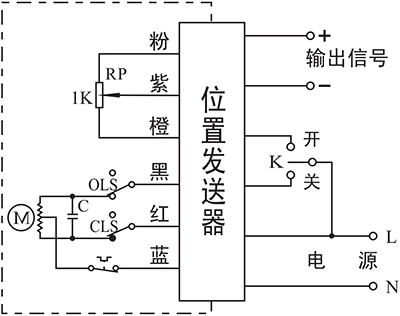
- Valdykite pavarą atidarymui arba uždarymui su K
- The real-time valve position will be send out as a 4-20mA signal.
Connecting Details:
- Connecting AC85-220V supply power line to L and neutral to N.
- Switch AC85-220V line to CLOSE(P2) to close the valve.
- Switch AC85-220V line to OPEN(P3) to open the valve.
- Connecting Output -/+ to the system to send out the real-time valve position.
C - Su 1KΩ/500Ω potenciometru
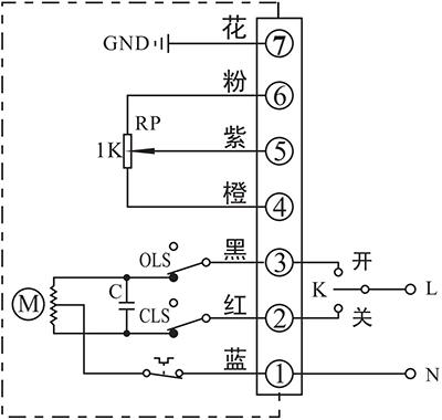
- Valdykite pavarą atidarymui arba uždarymui su K
- Realaus laiko vožtuvo padėtis bus siunčiama kaip potenciometro varžos vertė.
Connecting Details:
- Connecting AC85-220V supply power neutral to P1.
- Switch AC85-220V line to CLOSE(P2) to close the valve
- Switch AC85-220V line to OPEN(P3) to open the valve.
- P4 is the low side of potentiometer that is normally connected to signal GND.
- Connecting signal input of control system to P5. The resistance value between P4 and P5 will become higher as actuator opening the valve, while the value between P5 and P6 will become lower.
- P6 is the high side of potentiometer that is normally connected to signal power.
- Connect earth to P7.
D – Su potenciometru ir galinės padėties grįžtamuoju ryšiu
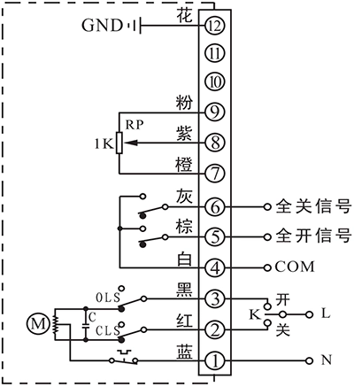
- Valdykite pavarą atidarymui arba uždarymui su K
- Realaus laiko vožtuvo padėtis bus siunčiama kaip potenciometro varžos vertė.
- Galinės padėties ATIDARYTA/UŽDARYTA išvesties gnybtas pasiųs įvykį pasyvaus signalo pavidalu, kai bus pasiekta galinė padėtis.
Connecting Details:
- Connecting AC85-220V supply power neutral to P1.
- Switch AC85-220V line to CLOSE(P2) to close the valve
- Switch AC85-220V line to OPEN(P3) to open the valve.
- P4 is the COM for passive contact signal of end-position OPEN/CLOSE which is normally connected to signal GND.
- P5 is end-position OPEN terminal which will be connected to COM when actuator reached end-position of open.
- P6 is end-position CLOSE terminal which will be connected to COM when actuator reached end-position of close.
- P7 is the low side of potentiometer that is normally connected to signal GND.
- Connecting signal input of control system to P8. The resistance value between P7 and P8 will become higher as actuator opening the valve, while the value between P8 and P9 will become lower.
- P9 is the high side of potentiometer that is normally connected to signal power.
- Connect earth to P12.
Pastaba:
- Punktyrinės dėžutės viduje esanti grandinė yra vidinė pavaros grandinė. O išorinė grandinė yra pavaros elektrinio prijungimo demonstracija.
- Jei turite kitų specifinių reikalavimų dėl prijungimo grandinės, susisiekite su mūsų technine pagalba.


 English (UK)
  香港中文
香港中文  繁體中文
繁體中文  English (Canada)
  English (South Africa)
  English (Australia)
  English (New Zealand)
  English
  Español de Puerto Rico
  Français du Canada
  Español de México
  Español de Chile
  Español de Colombia
  Español de Uruguay
  עִבְרִית
  Nederlands (België)
  Français de Belgique
  Eesti
Eesti  Latviešu valoda
  Lietuvių kalba
  Français
  Deutsch
  Norsk nynorsk
  Deutsch (Österreich)
  Slovenčina
  Deutsch (Schweiz)
  Italiano