


1. Réglage de la limite électrique de précision

Réglage de la fermeture complète :
Utiliser la poignée pour amener le robinet en position de fermeture complète.
Desserrez la vis de blocage du plateau de la balance et ajustez le plateau de la balance de manière à ce que l'aiguille s'aligne sur le point de référence. 0 marque (direction SHUT). Ensuite, serrez la vis.
L'utilisation d'un Clé hexagonale de 2 mm, tourner le arbre de réglage de fermeture (S) dans le sens des aiguilles d'une montre jusqu'à la butée D1 tourne dans le sens des aiguilles d'une montre et déclenche K2 et K1 séquentiellement, en produisant un son de clic.
Cessez de tourner lorsque K1 clicsLe réglage de la position de fermeture complète est terminé.
Réglage de l'ouverture totale :
Utilisez la poignée pour amener la vanne en position d'ouverture complète de manière à ce que l'aiguille s'aligne sur le repère de l'aiguille. 0 marque (sens OUVERT).
Utiliser un Clé hexagonale de 2 mm pour faire tourner le arbre de réglage de l'ouverture dans le sens inverse des aiguilles d'une montre jusqu'à l'arrêt du voyage D2 tourne dans le sens inverse des aiguilles d'une montre et déclenche K4 et K3 de manière séquentielle.
Arrêter le réglage lorsque K3 clicset terminer le réglage de la position d'ouverture totale.
2. Réglage de la limite électrique de la position intermédiaire
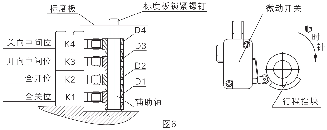
Réglage D1 (position de fermeture complète) :
Amener le robinet en position de fermeture complète et aligner le pointeur avec 0 (direction SHUT).
Desserrer le Vis de butée D1, tourner D1 dans le sens des aiguilles d'une montreet s'arrêter lorsque K1 clics.
Serrer la vis D1 pour fixer la butée.
Réglage D2 (position d'ouverture complète) :
Amener le robinet en position d'ouverture complète et aligner le pointeur avec 0 (sens OUVERT).
Desserrer le Vis de butée D2, tourner D2 dans le sens inverse des aiguilles d'une montreet s'arrêter lorsque Clics K2.
Serrer la vis D2 pour fixer la butée.
Ajustements D3 & D4 (positions intermédiaires) :
Déplacer la vanne légèrement éloigné de la pleine ouverture ou de la pleine fermeture par 2 degrés à l'aide de la poignée.
Ajuster D3 dans le sens inverse des aiguilles d'une montre (pour le sens de fermeture) jusqu'à ce que K3 clicspuis le verrouiller.
Ajuster D4 dans le sens des aiguilles d'une montre (pour le sens d'ouverture) jusqu'à ce que K4 clicspuis le verrouiller.
Note spéciale :
Si les positions d'ouverture et de fermeture complètes de la vanne ne correspondent pas à celles de l'actionneur, procédez au réglage en suivant les étapes suivantes 1 ou 2 ci-dessus.
Les interrupteurs de fin de course intermédiaires fournissent des signaux de contact sec, tandis que les interrupteurs de fin de course d'ouverture/fermeture complète contrôlent la position de la vanne.
Modèles A, C, E et F n'ont pas d'interrupteur de fin de course intermédiaire ou de butée de fin de course.
3. Réglage du potentiomètre (pour les modèles C et D)
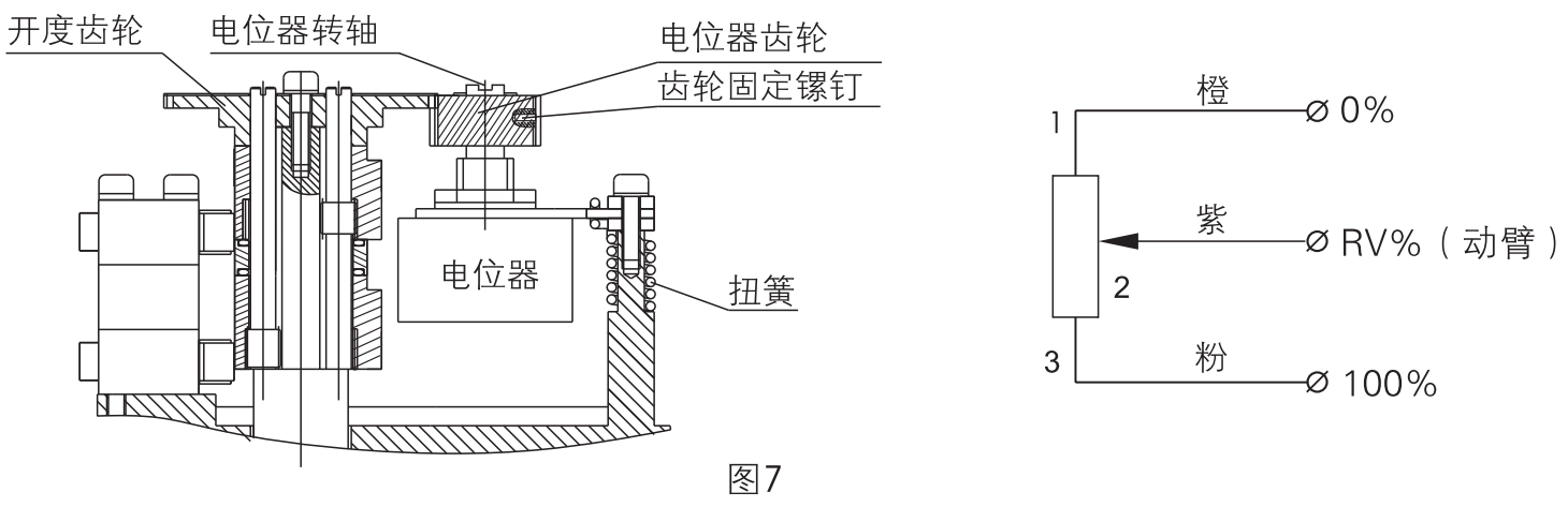
Placer l'actionneur en position 50% (à mi-chemin).
S'assurer que l'engrenage du potentiomètre s'engrène correctement avec l'engrenage de position (la vis de fixation de l'engrenage est tournée vers l'extérieur pour faciliter le serrage).
Mesurer la résistance entre les bornes 1 et 3 du potentiomètre à l'aide d'un multimètre et noter la valeur R.
Connectez le multimètre à la borne 2 et à n'importe quelle autre borne, puis tournez lentement l'arbre du potentiomètre.
Arrêter lorsque la lecture atteint R/2 ±2Ω, puis bloquer la vis de fixation de l'engrenage.
Note spéciale :
- Les actionneurs de modèle E n'ont pas d'interrupteur de fin de course ni de butée de fin de course.
- Ne pas ajuster le potentiomètre ou les engrenages à moins que cela ne soit nécessaire.
4. Réglage des butées mécaniques
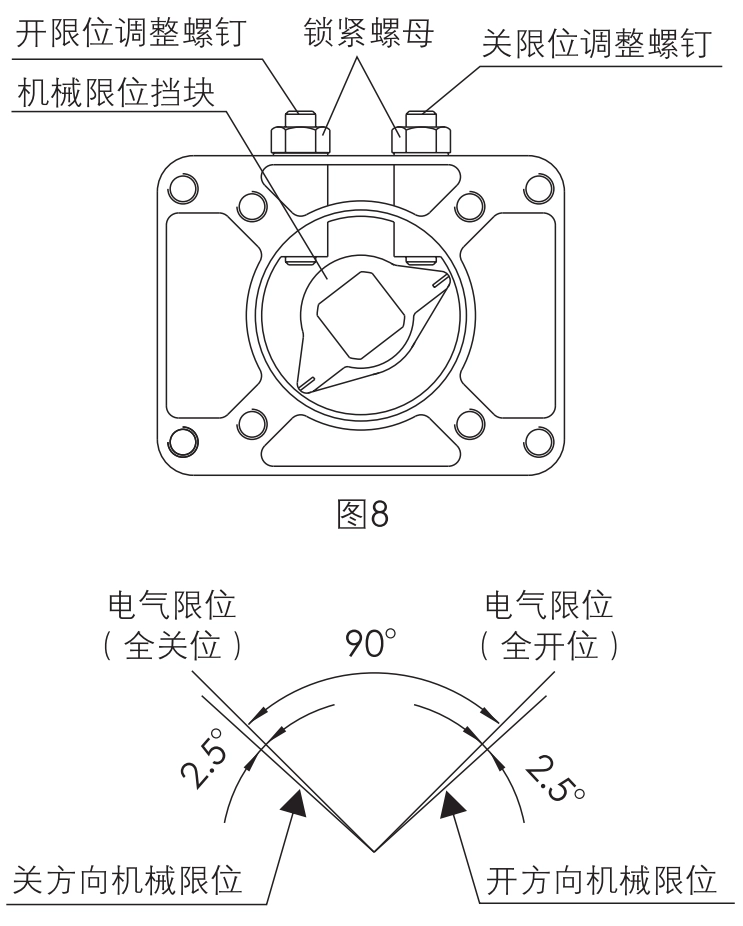
Déplacer le robinet vers le position complètement fermée jusqu'à ce que le Le commutateur de fin de course K1 s'enclenche.
Desserrer le écrou de blocage droit et tourner le vis de limite de fermeture dans le sens des aiguilles d'une montre jusqu'à ce qu'il touche la butée mécanique.
Ensuite, tourner la vis un demi-tour dans le sens inverse des aiguilles d'une montre l'arrêt mécanique est donc 2,5° derrière la limite électrique. Serrer l'écrou.
Répétez les mêmes étapes pour le position complètement ouverte sur le côté gauche.
Note spéciale :
- La limite mécanique doit être légèrement en retrait la limite électrique (voir diagramme 9).
- Si la butée mécanique est trop tôt ou aligné sur la limite électriquele moteur peut décrocher, surchauffer ou même griller.
5. Test de fonctionnement
Câbler correctement l'actionneur en fonction de l'annexe A. schéma du circuit de contrôle à l'intérieur de la couverture.
Tourner l'interrupteur en position "Fermer → L'actionneur entraîne la vanne dans le sens des aiguilles d'une montre pour fermer jusqu'à K1 clics et s'arrête.
Tourner l'interrupteur en position "Ouvert" → L'actionneur entraîne la vanne dans le sens inverse des aiguilles d'une montre pour ouvrir jusqu'à K3 clics et s'arrête.
Si le l'échelle de l'indicateur ne correspond pas à la position réelle de la vanne, desserrer le vis du plateau central de la balance et le réaligner pour un positionnement précis.


 鄂公网安备 42018502006527号