
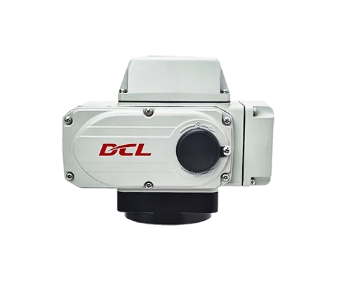

Quick Turn Actuator
Used in scenarios in which valve or damper should be quickly regulated
Utilisé directement à l'extérieur sans protection supplémentaire
Applicable aux vannes à demi-tour
IP68
Direction du mouvement
Tour partiel
Amortisseur
0 - 90° | 0 - 360°
Operating Time/Torque
2S~12S
15~1200Nm
Type de fonction
Modulation
Avancement par à-coups - Positionnement
On - Off
Tension d'alimentation
24 V CC
24 V CA
110 V CA
220 V CA
380 V CA
Signal d'entrée/sortie
4~20mA
0~10V
Interface d'E/S
Operational with fieldbus
Modbus-RTU
Modbus-ASCII
CAN
Ethernet
Options supplémentaires
Over-torque Protection
Fail Safe Return
Déshumidification
Diagnostic
Type de fonction
Modulation
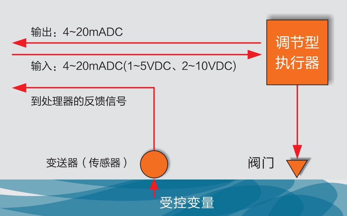
The actuator read the target position value from control system through 4-20mA, 2-10V or field bus such as modbus, ethernet and etc.
Then actuator drive the valve to the target position with interior control algorithm.
The actuator will always output the real-time valve position through 4-20mA, 2-10V or field bus.
Operated in type of duty S4, the actuator can starts 1200 times per hour.
On - Off
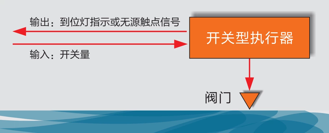
The actuator read the open or close requirement from control system through IO interface such as passive signal or 24VDC/220VAC active signal.
Then actuator drive the valve to the end-position of OPEN or CLOSE as input signal required.
The actuator will output a feedback signal of OPEN or CLOSE when end-position been reached.
Operated in type of duty S2, the actuator can drive valve continuously for 15 minutes.
Avancement par à-coups - Positionnement
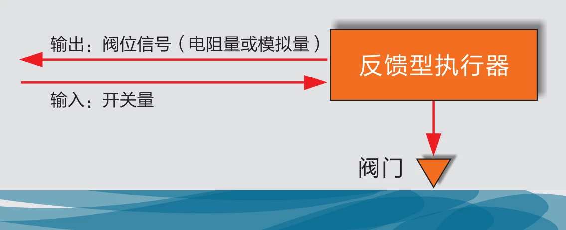
The actuator read the inching OPEN or CLOSE signal from control system through IO interface inputted with 24VDC/220VAC active signal.
Then actuator drive the valve with a stepping way specified by the input inching signal.
The actuator will always output the real-time valve position as a potentiometer resistance value or 4-20mA/2-10V value.
Operated in type of duty S2, the actuator can drive valve continuously for 15 minutes.
Features
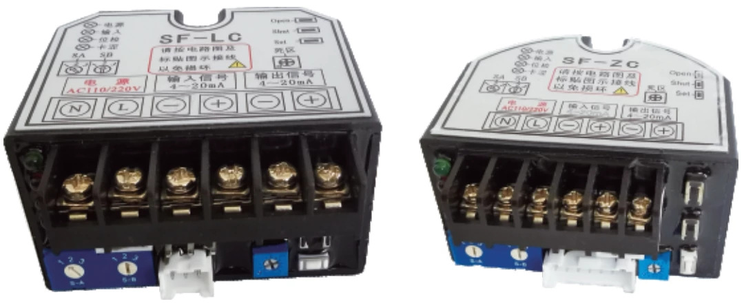
Fully Capsulated Control Unit
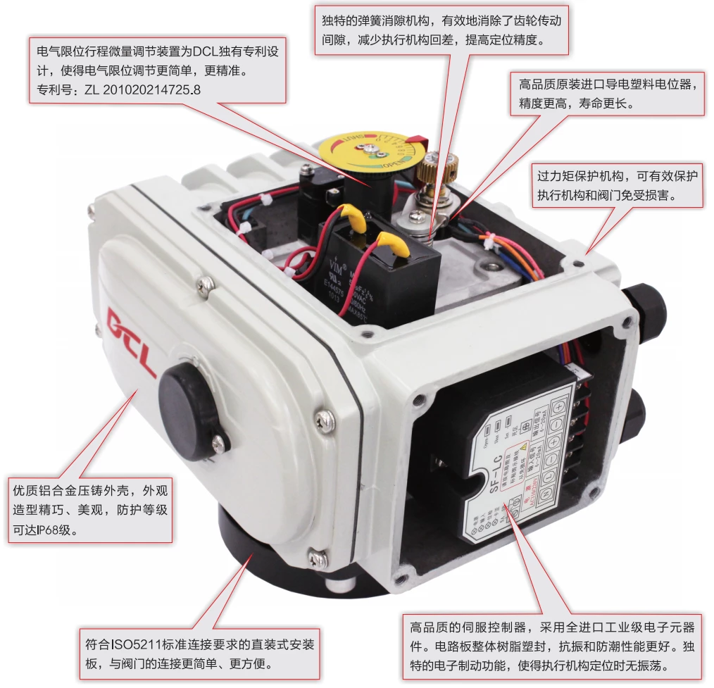
The control unit is fully encapsulated with polyurethane. This greatly enhanced proof performance against moisture, condensation, salt and vibration. So it is applicable in harsh environments such as high humidity, dust, strong temperature changing, vibration, etc.
With 6kV EFT and surge protection circuit, the stable control à the valve can be ensured even in worst electromagnetic environment.
By self-adjustment algorithm, the actuator can keep the precision against different loads conditions and mechanical wear by time.
Easy-to-use Limit Switch
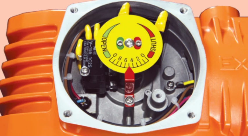
With DCL’s patented limit switch design, the actuator’s end position of open and close can be easily configured only with a hexagonal wrench.
In the meantime the micro adjustment feature of limit switch can improve the precision when setting the end-position.
Patent No. ZL 201020214725.8
Motor with Over Temperature Protection
DCL specially design the motor to fit the actuator requirement so that the motor in DCL actuator can supply a high start torque while maintain a high efficiency in the start phase to make the temperature rise as low as possible. In the meantime the motor have a small moment of inertia to make sure the high precision in modulation.
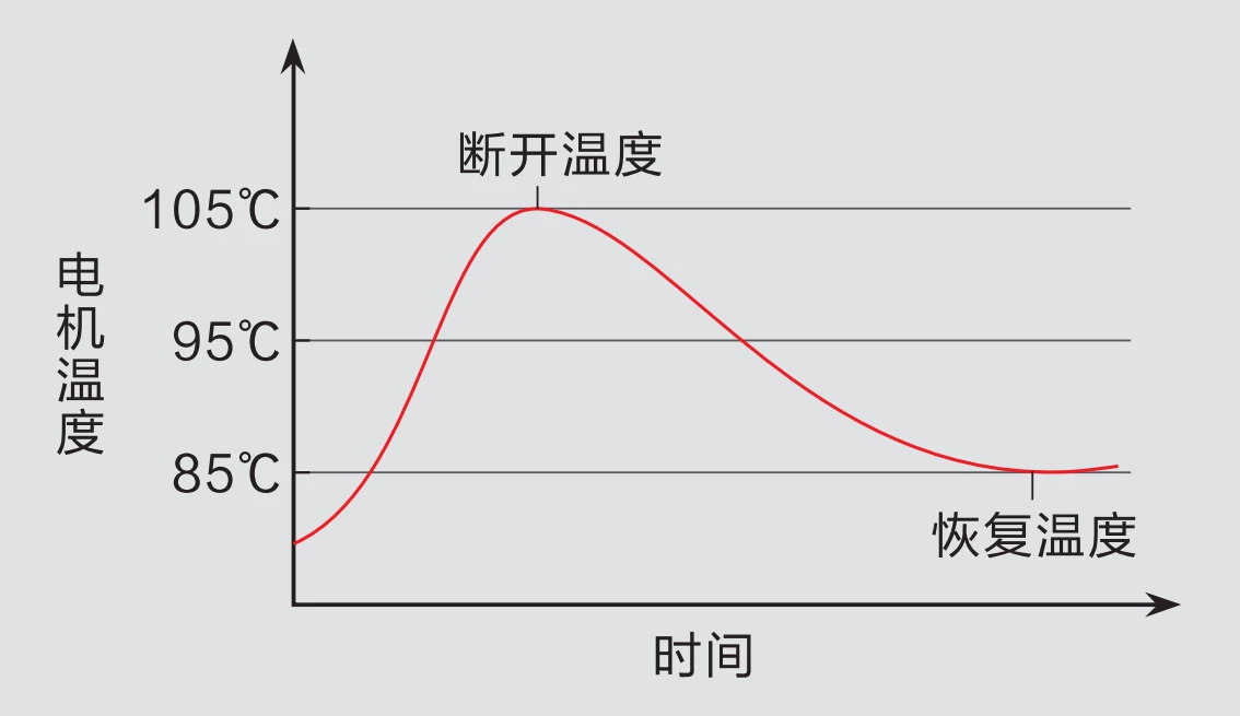
There is an over temperature protection device mounted in the motor which will cut the power supply when the motor temperature goes higher then the limited temperature(105℃/85℃ can be selected up on the application scenario) and connect the power supply again when the temperature recovered below the Normal temperature.
Dual Position Limiter
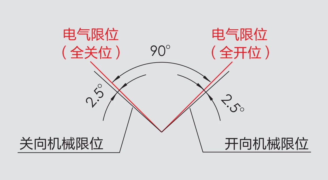
There are 2 position limit devices to protect valve from damage by operation over swing angle.
Electric limit switch are mounted on the both end-position of OPEN and CLOSE. So the power supply to motor will be cut off to stop driving the valve after limited end-position was reached.
Also there are 2 mechanical limiters mounted on the output shaft to protect the valve from swing over stroke range. The mechanical limiter will not take effect in normal operation cause the electric limit switch is ahead of the mechanical limiter and will be triggered before the output shaft can reach the mechanical limited positon.
Options supplémentaires
Over-torque Protection
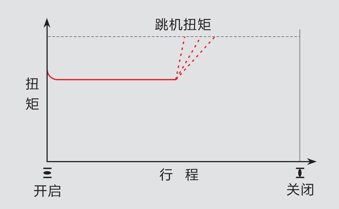
When the valve is stuck by some reason such as solid impurities in the liquid or malfunction on some mechanical parts, the torque on output shaft of actuator will increased sharply beyond the limit torque value when driving the valve, then the actuator would trig an over torque protection to stop driving the valve in order to protect the valve from damage.
Dehumidifying
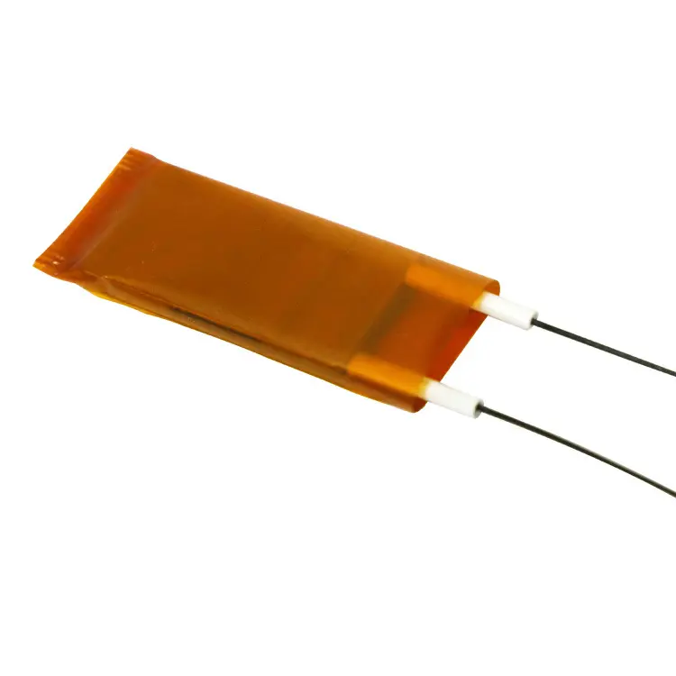
You can choose a dehumidifying option on DCL actuator. Then a electric PTC heater will be mounted in the actuator to reduce humidity to protect circuit from malfunction in high range of temperature changing circumstance due to condensation.
The PTC heater will be in working mode as long as power is supplied to actuator.
Circuit Diagram
Modulation
E - Modulation avec une unité de contrôle
- Entrée : 4~20 mA / 0~10 V
- Sortie : 4~20 mA / 0~10 V
- Bus de terrain : Modbus / CAN
- IIoT : DTU WiFi/LoRa/4G
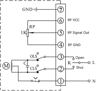
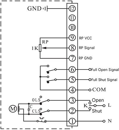
Avancement par à-coups et positionnement
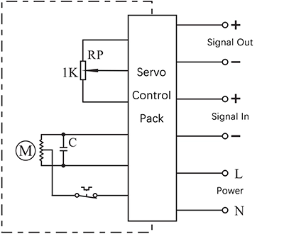
F - Avec une unité de positionnement
- Actionneur de commande pour ouvrir ou fermer avec K
- The real-time valve position will be send out as a 4-20mA signal
C - Avec un potentiomètre 1KΩ/500Ω
- Actionneur de commande pour ouvrir ou fermer avec K
- La position de la vanne en temps réel sera transmise sous forme de valeur de résistance du potentiomètre.
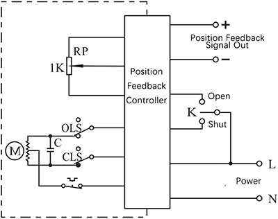
D - Avec un potentiomètre et un retour de position finale
- Actionneur de commande pour ouvrir ou fermer avec K
- La position de la vanne en temps réel sera transmise sous forme de valeur de résistance du potentiomètre.
- La borne de sortie de la position finale OUVERTE/FERMÉE enverra l'événement sous forme de signal passif lorsque la position finale sera atteinte.
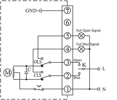
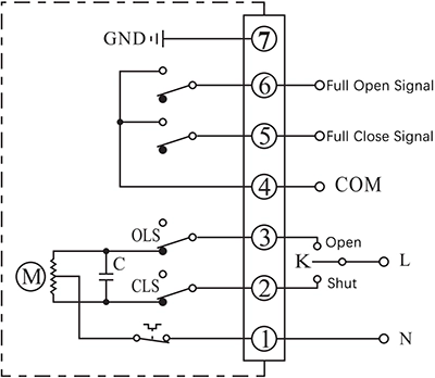
MARCHE - ARRÊT
A - Avec 2 sorties de signal de position finale actives
- Actionneur de commande pour ouvrir ou fermer avec K
- La borne de sortie de la position finale OUVERTE/FERMÉE enverra l'événement sous la forme d'un signal actif de 220 V CA lorsque la position finale sera atteinte.
B - Avec 2 interrupteurs de fin de course passifs
- Actionneur de commande pour ouvrir ou fermer avec K
- La borne de sortie de la position finale OUVERTE/FERMÉE enverra l'événement sous forme de signal passif lorsque la position finale sera atteinte.
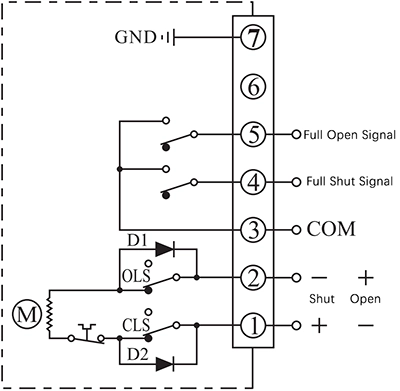
Moteur à courant continu G avec 2 interrupteurs de fin de course
- Actionneur de commande pour s'ouvrir ou se fermer en fonction du sens d'alimentation entre les bornes 1 et 2
- La borne de sortie de la position finale OUVERTE/FERMÉE enverra l'événement sous forme de signal passif lorsque la position finale sera atteinte.
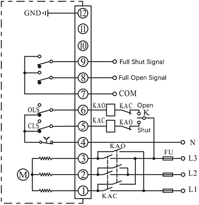
Moteur triphasé 380 V CA H avec 2 interrupteurs de fin de course
- Actionneur de commande permettant l'ouverture ou la fermeture par un onduleur externe afin de modifier la phase de l'alimentation électrique.
- La borne de sortie de la position finale OUVERTE/FERMÉE enverra l'événement sous forme de signal passif lorsque la position finale sera atteinte.
Note:
- Le circuit à l'intérieur du cadre en pointillés représente le circuit interne de l'actionneur. Le circuit extérieur illustre le branchement électrique nécessaire à l'utilisation de l'actionneur.
- Si vous avez d'autres exigences spécifiques concernant le raccordement du circuit, n'hésitez pas à contacter notre assistance technique.
Basic Parameters
| Model | Angle de balancement | Operating Time/Torque | Duty Type | Tension d'alimentation | Signal d'entrée/sortie | Options supplémentaires |
|---|---|---|---|---|---|---|
| DCL-K05 | 0 - 270° | 6s/30Nm Optionnel avec 2s/15Nm 3s/15Nm 5s/30Nm | MARCHE - ARRÊT Modulation Avancement par à-coups - Positionnement | 24 V CC 24 V CA 110 V CA 220 V CA 380 V CA | 4-20 mA 0-10V Interface d'E/S Optional with field bus Modbus-RTU Modbus-ASCII CAN Ethernet | Over torque protection Fail Safe Return Déshumidification Bus de terrain |
| DCL-K10 | 0 - 90° | 2s/25Nm Optionnel avec 4s/50Nm 8s/80Nm | MARCHE - ARRÊT Modulation Avancement par à-coups - Positionnement | 24 V CC 24 V CA 110 V CA 220 V CA 380 V CA | 4-20 mA 0-10V Interface d'E/S Optional with field bus Modbus-RTU Modbus-ASCII CAN Ethernet | Over torque protection Fail Safe Return Déshumidification Bus de terrain |
| DCL-K20 | 0 - 90° | 8s/200Nm Optionnel avec 2s/50Nm 4s/100Nm | MARCHE - ARRÊT Modulation Avancement par à-coups - Positionnement | 24 V CC 24 V CA 110 V CA 220 V CA 380 V CA | 4-20 mA 0-10V Interface d'E/S Optional with field bus Modbus-RTU Modbus-ASCII CAN Ethernet | Over torque protection Fail Safe Return Déshumidification Bus de terrain |
| DCL-K40 | 0 - 90° | 8s/330Nm Optionnel avec 2s/80Nm 4s/160Nm | MARCHE - ARRÊT Modulation Avancement par à-coups - Positionnement | 24 V CC 24 V CA 110 V CA 220 V CA 380 V CA | 4-20 mA 0-10V Interface d'E/S Optional with field bus Modbus-RTU Modbus-ASCII CAN Ethernet | Over torque protection Fail Safe Return Déshumidification Bus de terrain |
| DCL-K100 | 0 - 90° | 12s/1200Nm Optionnel avec 4s/500Nm 8s/800Nm | MARCHE - ARRÊT Modulation Avancement par à-coups - Positionnement | 24 V CC 24 V CA 110 V CA 220 V CA 380 V CA | 4-20 mA 0-10V Interface d'E/S Optional with field bus Modbus-RTU Modbus-ASCII CAN Ethernet | Over torque protection Fail Safe Return Déshumidification Bus de terrain |
Recommend actuator to drive a butterfly valve
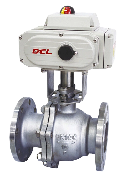
Recommend actuator to drive a Ball valve
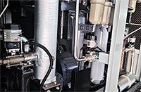
Recommend actuator to drive a ventilation valve
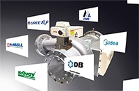
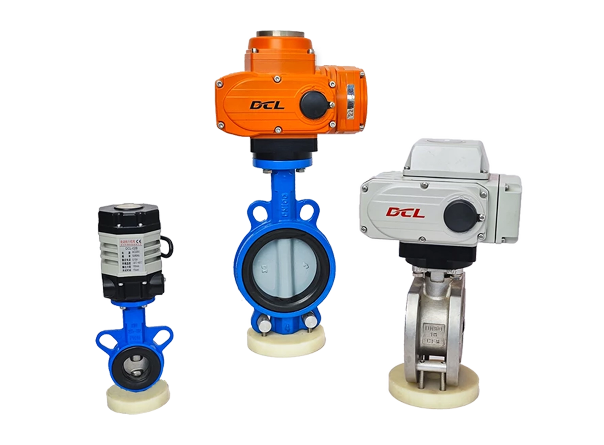
Recommend valve to be driven by DCL weather-proof actuator
Note: The recommendations in the above table is for reference only in common application scenario, the specific torque needed to drive the valve is depended up on the real application case.
It is recommended to choose an actuator with 1.1-1.3 times of torque than the value that was finalized after evaluation of torque requirement of valve and liquid pressure in the pipe. This would improve the robust performance in most worst case.
Choose an actuator based on different torque
6s/30Nm
———————–
Optionnel avec
2s/15Nm
3s/15Nm
5s/30Nm
2s/25Nm
———————–
Optionnel avec
4s/50Nm
8s/80Nm
8s/200Nm
———————–
Optionnel avec
2s/50Nm
4s/100Nm
8s/330Nm
———————–
Optionnel avec
2s/80Nm
4s/160Nm
12s/1200Nm
———————–
Optionnel avec
4s/500Nm
8s/800Nm