








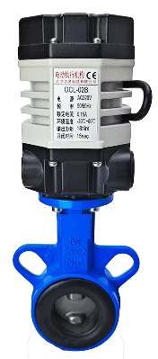
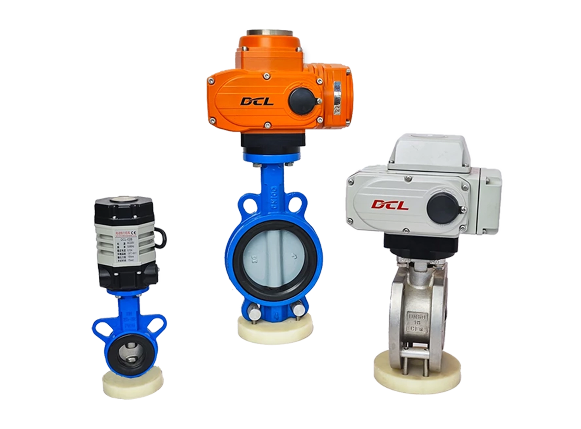
This guide is applicable to the DCL Ultra-Small Series actuators, with the following models:
DCL-02A
DCL-02B
DCL-02G
Common Faults and Troubleshooting Methods
| Fault | Possible Causes | Troubleshooting Methods |
|---|---|---|
| Actuator does not open or close on initial start | 1. Incorrect wiring | Check the wiring according to the actuator’s wiring diagram. |
| 2. Incorrect power supply | Ensure the power supply voltage is within ±10% of the actuator’s rated voltage and the current is 3 times the rated current. | |
| 3. Faulty control switch or relay | Measure the input voltage at the actuator’s control terminal using a multimeter to verify it matches expectations. | |
| 4. Control system mismatch | Test the actuator with a mechanical switch. If it operates normally, verify the control system’s output logic. | |
| 5. Multiple actuators or actuators and other devices connected in parallel | Switch actuators should use single-path control and not be wired in parallel, as this affects the startup capacitor. | |
| Actuator can only open or close | 1. Incorrect wiring | Check the wiring using the actuator’s wiring diagram. |
| 2. Incorrect full open/close cam setting | Refer to the “How to Set Electric Switch-Type Valves” guide and correctly set the cam positions. | |
| Actuator stops in the middle of travel | 1. Valve jammed | Check for blockages in the valve. Clear any obstruction and retry after the actuator’s overload protection cools. |
| 2. Solid material in fluid causing valve jam | Inspect the fluid for solid particles causing valve jams. Clear the jam and retry after the actuator’s overload protection cools. | |
| 3. Incorrect full open/close stopper setting | Refer to the “How to Set Electric Switch-Type Valves” guide and correctly adjust the stopper positions. | |
| Unable to turn actuator using the handle | 1. Solid material in fluid causing valve to seize | Check for blockage in the valve. Clear the blockage and retry after the actuator’s overload protection cools. |
| 2. Valve seizing | Inspect the valve for jamming. Clear the blockage and retry after the actuator’s overload protection cools. | |
| 3. Damaged actuator reduction mechanism | Remove the actuator from the valve and rotate the handle. If it doesn’t move, replace the actuator. | |
| No position feedback signal | 1. Incorrect wiring at the switch | Check the wiring according to the actuator’s wiring diagram. |
| 2. Incorrect full open/close cam setting | Refer to the “How to Set Electric Switch-Type Valves” guide and set the cam position correctly. | |
| 3. Overcurrent causing position feedback switch damage | 1. Check if the full open/close cam is pressing on the position feedback switch correctly, as per the guide. | |
| 2. Measure if the position feedback circuit is closed. |
Verify that the operating conditions meet the parameter requirements.
Electric actuators may fail due to improper use or being used in incorrect operating conditions. When used within the operating conditions defined in the product specifications, the actuator can be expected to operate reliably for an extended period without failure.
Supply Voltage: The voltage from the power supply must be within the rated operating voltage range of the actuator. Overvoltage or undervoltage may shorten the actuator’s lifespan.
Supply Current: The starting current of the motor is significantly higher than the rated current. To ensure reliable operation, use a power supply capable of delivering at least 3 times the rated current of the actuator.
Temperature: Ensure the actuator operates within its rated temperature range. Using the actuator outside this range may result in poor performance, reduced lifespan, and eventual failure.
Environment: The DCL switch-type actuator has an IP67 weatherproof rating, making it suitable for both indoor and outdoor applications. It offers a degree of protection against rain and splashing water, helping to prolong the actuator’s life by shielding it from rain, snow, ice, and UV (sunlight). However, in highly corrosive environments, electronic components may fail prematurely. Non-explosion-proof actuators should not be used in explosive environments.
Duty Cycle: The DCL switch-type actuator has a duty cycle of 70% (42 seconds of operation per minute, followed by 18 seconds of rest). Exceeding this duty cycle may cause the motor to enter thermal protection.
Check the Wiring of the Actuator
Ensure the actuator is wired correctly according to the wiring diagram provided by the manufacturer. Follow these steps to verify the wiring:
Power Supply:
Check the power supply connections to ensure they match the actuator’s required input voltage and current.
Control Connections:
Verify that the input and output control connections are securely attached and in the correct configuration as per the actuator’s wiring diagram.
Signal Wiring:
Check the wiring for control signals, such as 4-20mA or 0-10V, depending on the actuator’s specifications.
Confirm that there are no loose connections or short circuits.
Grounding:
Ensure that the actuator is properly grounded to prevent electrical interference or damage.
Connections to Other Equipment:
If the actuator is connected to other devices, make sure those connections are also correct and do not cause interference or power issues.
If the wiring appears correct, but the actuator is still malfunctioning, further troubleshooting or assistance from a technician may be necessary.
A - Mit 2 aktiven Endpositionssignalausgängen
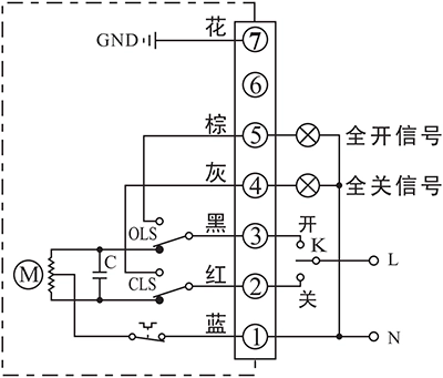
- Steueraktuator zum Öffnen oder Schließen mit K
- Der Ausgangsanschluss der Endposition OPEN/CLOSE sendet das Ereignis als aktives 220VAC-Signal aus, sobald die Endposition erreicht ist.
Verbindungsdetails:
- Anschluss des Neutralleiters der Wechselstromversorgung AC85-220V an P1.
- Schalten Sie die AC85-220V-Leitung auf GESCHLOSSEN (P2), um das Ventil zu schließen.
- Schalten Sie die AC85-220V-Leitung auf OPEN(P3), um das Ventil zu öffnen.
- P5 ist der Endpositionsanschluss OPEN, der eine AC220V-Quelle ausgibt, mit der eine Kontrollleuchte angesteuert werden kann, wenn der Aktor die Endposition offen erreicht hat.
- P6 ist der Endpositions-OPEN-Anschluss, der eine AC220V-Quelle ausgibt, mit der eine Kontrollleuchte angesteuert werden kann, wenn der Aktor die Endposition geschlossen erreicht hat.
- Schließen Sie die Erde an P7 an.
B - With 2 passive end-position switche
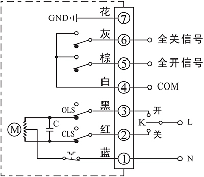
- Steueraktuator zum Öffnen oder Schließen mit K
- Der Ausgangsanschluss der Endposition OPEN/CLOSE sendet das Ereignis als passives Signal aus, sobald die Endposition erreicht ist.
Verbindungsdetails:
- Anschluss des Neutralleiters der Wechselstromversorgung AC85-220V an P1.
- Schalten Sie die AC85-220V-Leitung auf GESCHLOSSEN (P2), um das Ventil zu schließen.
- Schalten Sie die AC85-220V-Leitung auf OPEN(P3), um das Ventil zu öffnen.
- P4 ist der COM-Anschluss für das passive Kontaktsignal der Endposition OPEN/CLOSE, das normalerweise mit dem Signal GND verbunden ist.
- P5 ist der Endpositionsanschluss OPEN, der mit COM verbunden wird, wenn der Aktor die Endposition offen erreicht hat.
- P6 ist der Endpositionsanschluss CLOSE, der mit COM verbunden wird, wenn der Aktor die Endposition CLOSE erreicht hat.
- Schließen Sie die Erde an P7 an.
G - Gleichstrommotor mit 2 Endschaltern
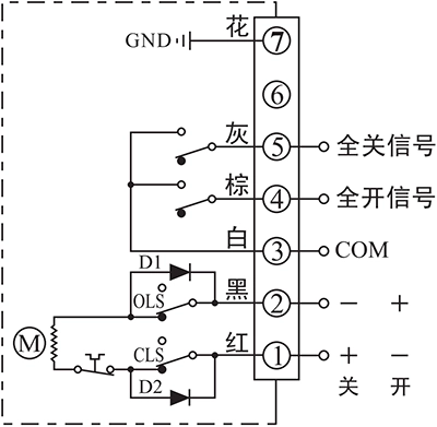
- Der Stellantrieb wird durch die Richtung der Versorgungsspannung zwischen den Klemmen 1 und 2 zum Öffnen oder Schließen gesteuert.
- Der Ausgangsanschluss der Endposition OPEN/CLOSE sendet das Ereignis als passives Signal aus, sobald die Endposition erreicht ist.
Verbindungsdetails:
- Durch Anschließen von DC24V+ an P1 und DC24V- an P2 wird das Ventil geschlossen.
- Durch Anschließen von DC24V+ an P2 und DC24V- an P1 wird das Ventil geschlossen.
- P3 ist der COM-Anschluss für das passive Kontaktsignal der Endposition OPEN/CLOSE, das normalerweise mit dem Signal GND verbunden ist.
- P4 ist der Endpositionsanschluss OPEN, der mit COM verbunden wird, wenn der Aktor die Endposition offen erreicht hat.
- P5 ist der Endpositionsanschluss CLOSE, der mit COM verbunden wird, wenn der Aktor die Endposition CLOSE erreicht hat.
- Schließen Sie die Erde an P7 an.
Notiz:
- Der Schaltkreis im gestrichelten Kasten ist der interne Schaltkreis des Aktuators. Der Schaltkreis außerhalb des Kastens veranschaulicht die elektrische Verbindung zum Betrieb des Aktuators.
- Falls Sie weitere spezielle Anforderungen an die Anschlussschaltung haben, wenden Sie sich bitte an unseren technischen Support.
When conducting troubleshooting on-site, feel free to contact our technical service personnel immediately for assistance in diagnosing and resolving the issue.
Contact phone number: 13026331611 (Mr. Chen)


 English (UK)
  香港中文
香港中文  繁體中文
繁體中文  English (Canada)
  English (South Africa)
  English (Australia)
  English (New Zealand)
  English
  Español de Puerto Rico
  Français du Canada
  Español de México
  Español de Chile
  Español de Colombia
  Español de Uruguay
  עִבְרִית
  Nederlands (België)
  Français de Belgique
  Eesti
Eesti  Latviešu valoda
  Lietuvių kalba
  Français
  Deutsch
  Norsk nynorsk
  Deutsch (Österreich)
  Slovenčina
  Deutsch (Schweiz)
  Italiano