
Produkte

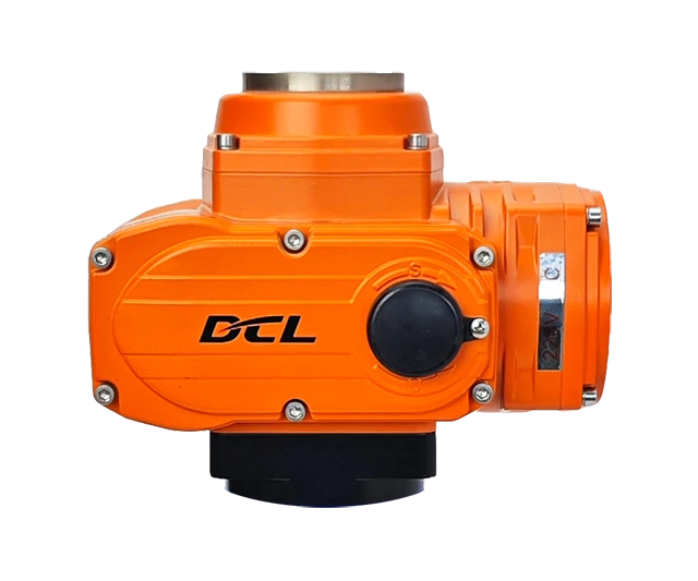
Technical Parameters

Explosion Proof GradeExd II CT4Gb
Power SupplyDC24V, AC24V, AC110V, AC220V, AC380V
Standard Torque/Time100Nm/30S
Optional Torque/Time50Nm/15S, 100Nm/60S
Rotation Angle RangeAdjustable from 0 to 90 degrees
Motor Power/CurrentDC24V: 25W/2.20A
AC24V: 25W/2.12A
AC110V: 25W/0.57A
AC220V: 15W/0.30A
AC380V: 25W /0.10A
Control CircuitType A/B/C/D/E/F/G/H
Weight5.0kg
Insulation Resistance DC24V/AC24V: 100MΩ/250VDC
AC110V/AC220V/AC380V: 100MΩ/500VDC
Withstand VoltageDC24V/AC24V: 500VAC for 1 minute
Water Proof LevelIP68
Installation360 ° installation at any angle
Electrical Interface2-M20x1.5 explosion-proof plug, users should install corresponding explosion-proof cable connectors according to the selected cable during use
Working Temperature-20℃~+60℃
Optional FunctionDehumidification heater
Modulation Parameters
Eingangssignal4~20mA, 0~10V arbitrary calibration
output Signal4~20mA, 0~10V arbitrary calibration
Bus485/Modbus/CAN
Internet of ThingsWIFI/LoRA/4G
Basic Error≤±1%
Return Error≤1%
HysteresisAdjustable from 0.5% to 5.0%
Reposition Times0 times
Repeatability Error≤1%

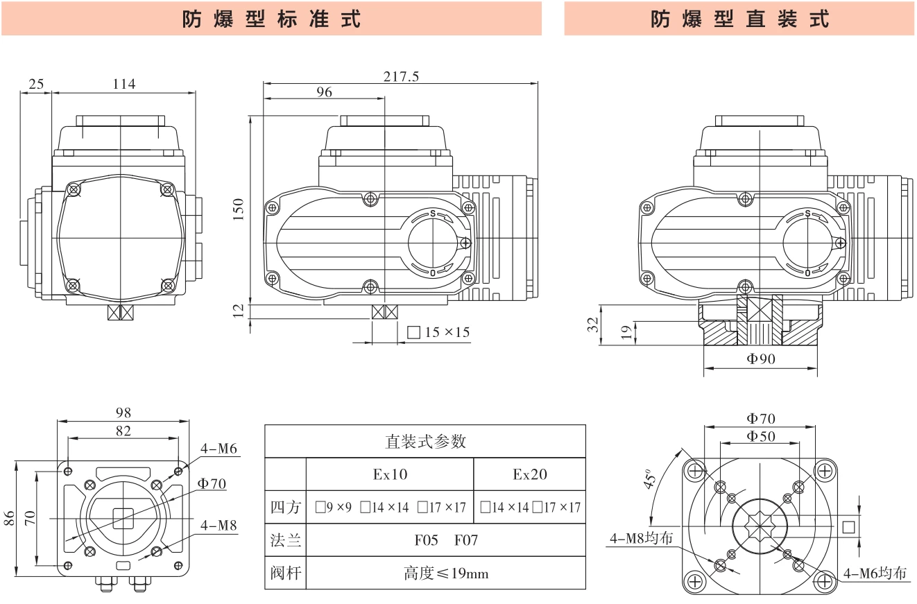
Dimensions

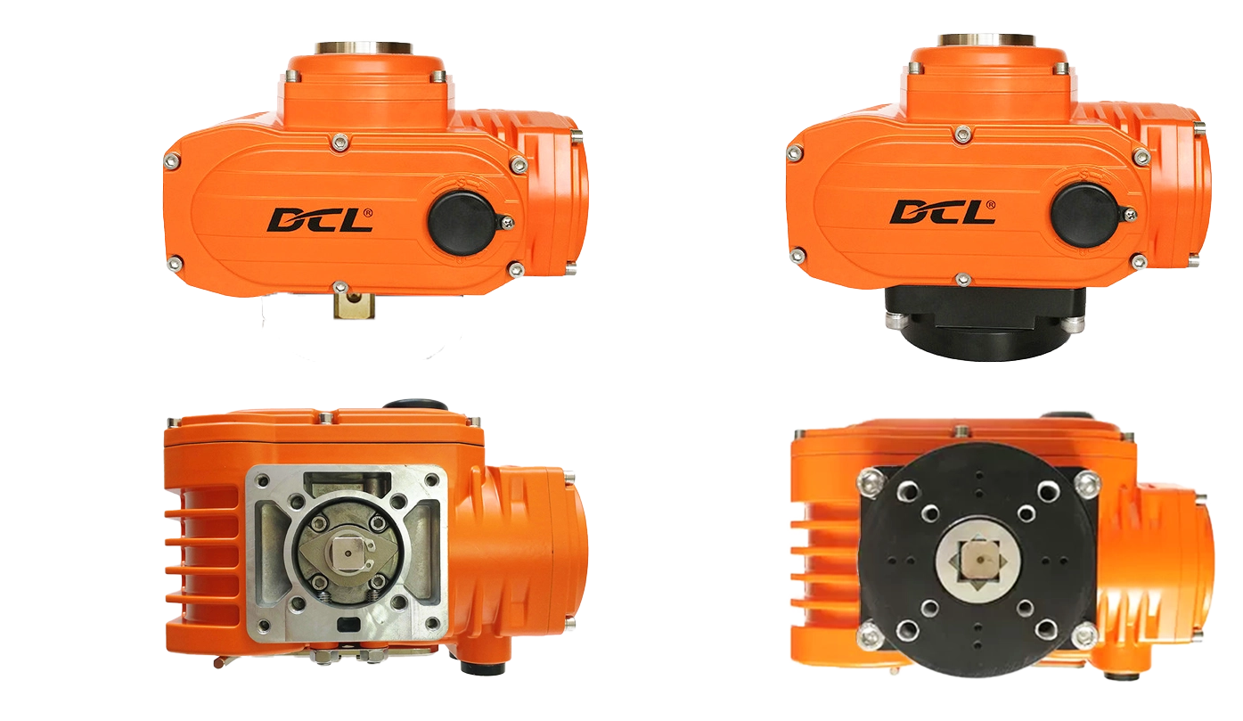
华易防爆执行器安装形式 | DCL Explosion-Proof Actuator Installation Demension
华易Exd II CT4Gb执行器 DCL-Ex10 DCL-Ex20 外型安装尺寸

Application Circuit

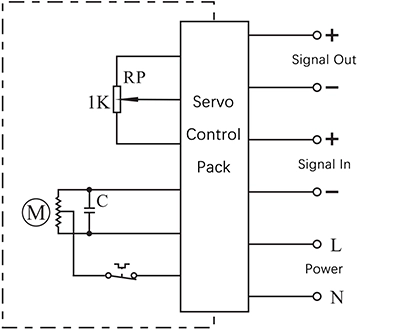
Modulieren

E - Modulating with a control unit

  • Input: 4~20mA / 0~10V
  • Output: 4~20mA / 0~10V
  • Field Bus:Modbus / CAN
  • IIot:WIFI/LoRA/4G DTU


Connecting Details:

  1. Connecting AC85-220V supply power line to L and neutral to N.
  2. Connecting 4-20mA/2-10V input signal source from control system to input-/+.
  3. Connecting Output -/+ to the system to send out the real-time valve position.

Inching and positioning

F - With a positioning unit

  • Control actuator to open or close with K
  • The real-time valve position will be send out as a 4-20mA signal.


Connecting Details:

  1. Connecting AC85-220V supply power line to L and neutral to N.
  2. Switch AC85-220V line to CLOSE(P2) to close the valve.
  3. Switch AC85-220V line to OPEN(P3) to open the valve.
  4. Connecting Output -/+ to the system to send out the real-time valve position.

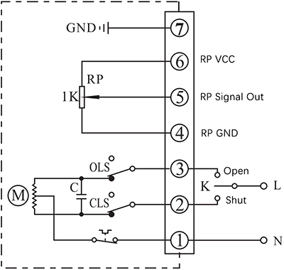
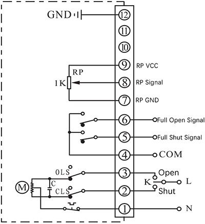
C - With a 1KΩ/500Ω potentiometer

  • Control actuator to open or close with K
  • The real-time valve position will be send out as a potentiometer resistance value


Connecting Details:

  1. Connecting AC85-220V supply power neutral to P1.
  2. Switch AC85-220V line to CLOSE(P2) to close the valve
  3. Switch AC85-220V line to OPEN(P3) to open the valve.
  4. P4 is the low side of potentiometer that is normally connected to signal GND.
  5. Connecting signal input of  control system to P5. The resistance value between P4 and P5 will become higher as actuator opening the valve, while the value between P5 and P6 will become lower.
  6. P6 is the high side of potentiometer that is normally connected to signal power.
  7. Connect earth to P7.

D - With a potentiometer and end-position feedback

  • Control actuator to open or close with K
  • The real-time valve position will be send out as a potentiometer resistance value
  • The output terminal of end-position OPEN/CLOSE will send out the event as a passive signal form when the end-position was reached.


Connecting Details:

  1. Connecting AC85-220V supply power neutral to P1.
  2. Switch AC85-220V line to CLOSE(P2) to close the valve
  3. Switch AC85-220V line to OPEN(P3) to open the valve.
  4. P4 is the COM for passive contact signal of end-position OPEN/CLOSE which is normally connected to signal GND.
  5. P5 is end-position OPEN terminal which will be connected to COM when actuator reached end-position of open.
  6. P6 is end-position CLOSE terminal which will be connected to COM when actuator reached end-position of close.
  7. P7 is the low side of potentiometer that is normally connected to signal GND.
  8. Connecting signal input of  control system to P8. The resistance value between P7 and P8 will become higher as actuator opening the valve, while the value between P8 and P9 will become lower.
  9. P9 is the high side of potentiometer that is normally connected to signal power.
  10. Connect earth to P12.

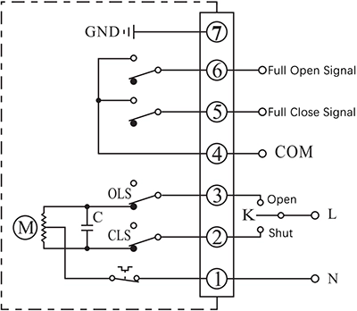
ON - OFF

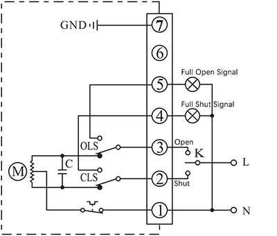
A - With 2 active end-position signal outputs

  • Control actuator to open or close with K
  • The output terminal of end-position OPEN/CLOSE will send out the event as a 220VAC active signal form when the end-position was reached.


Connecting Details:

  1. Connecting AC85-220V supply power neutral to P1.
  2. Switch AC85-220V line to CLOSE(P2) to close the valve
  3. Switch AC85-220V line to OPEN(P3) to open the valve.
  4. P5 is end-position OPEN terminal which will output a AC220V source which can be used to drive an Indication light when actuator reached end-position of open.
  5. P6 is end-position OPEN terminal which will output a AC220V source which can be used to drive an Indication light when actuator reached end-position of close.
  6. Connect earth to P7.

B - With 2 passive end-position switches

  • Control actuator to open or close with K
  • The output terminal of end-position OPEN/CLOSE will send out the event as a passive signal form when the end-position was reached.


Connecting Details:

  1. Connecting AC85-220V supply power neutral to P1.
  2. Switch AC85-220V line to CLOSE(P2) to close the valve
  3. Switch AC85-220V line to OPEN(P3) to open the valve.
  4. P4 is the COM for passive contact signal of end-position OPEN/CLOSE which is normally connected to signal GND.
  5. P5 is end-position OPEN terminal which will be connected to COM when actuator reached end-position of open.
  6. P6 is end-position CLOSE terminal which will be connected to COM when actuator reached end-position of close.
  7. Connect earth to P7.

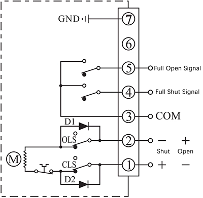
G - DC motor with 2 end-position switches

  • Control actuator to open or close by the supply power direction between the terminal 1 and 2
  • The output terminal of end-position OPEN/CLOSE will send out the event as a passive signal form when the end-position was reached.


Connecting Details:

  1. Connecting DC24V+ to P1 and DC24V- to P2 to close the valve.
  2. Connecting DC24V+ to P2 and DC24V- to P1 to close the valve.
  3. P3 is the COM for passive contact signal of end-position OPEN/CLOSE which is normally connected to signal GND.
  4. P4 is end-position OPEN terminal which will be connected to COM when actuator reached end-position of open.
  5. P5 is end-position CLOSE terminal which will be connected to COM when actuator reached end-position of close.
  6. Connect earth to P7.

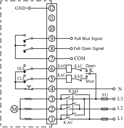
H - 3 phase 380VAC motor with 2 end-position switches

  • Control actuator to open or close by an external inverter to change the phase of supply power.
  • The output terminal of end-position OPEN/CLOSE will send out the event as a passive signal form when the end-position was reached.


Connecting Details:

  1. Connecting a 3 phase AC380V inverter output to P1, P2 and P3, then the actuator can be controlled to open or close the valve by change the 3 phase order.
  2. Connecting AC380V neutral to N(P4).
  3. P5 is used for cooperating with an external switch to control the inverter 3 phase order. This terminal is connected to N(P4) when actuator is not in end-position of CLOSE and disconnected from N(P4) after actuator reached end-position of CLOSE.
  4. P6 is used for cooperating with an external switch to control the inverter 3 phase order. This terminal is connected to N(P4) when actuator is not in end-position of OPEN and disconnected from N(P4) after actuator reached end-position of OPEN.
  5. P7 is the COM for passive contact signal of end-position OPEN/CLOSE which is normally connected to signal GND.
  6. P8 is end-position OPEN terminal which will be connected to COM when actuator reached end-position of open.
  7. P9 is end-position CLOSE terminal which will be connected to COM when actuator reached end-position of close.
  8. Connect earth to P12.

Note:

  • The circuit inside the dashed box is the internal circuit of actuator. While the circuit outside is a demonstration of electrical connection for using actuator.
  • If you have other specific requirements about connecting circuit, please feel free to contact our technical support. 

Choose another actuator with different torque​

50Nm/20S

————————–

Optional with

20Nm/4S

30Nm/10S

50Nm/60S

100Nm/30S

————————–

Optional with

50Nm/15S

100Nm/60S


200Nm/30S

————————–

Optional with

100Nm/15S

200Nm/60S


400Nm/30S

————————–

Optional with

200Nm/15S

400Nm/60S


Angebotsanfrage

Drücken Sie jetzt auf „Senden“. Wir bestätigen Ihnen später die Produktmodellnummer und den lokalen Händler und senden Ihnen dann das Angebot zu.

WhatsApp

Scannen Sie den QR-Code, um jetzt mit unserem Techniker zu chatten...

Angebotsanfrage

Drücken Sie jetzt auf „Senden“. Wir bestätigen Ihnen später die Produktmodellnummer und den lokalen Händler und senden Ihnen dann das Angebot zu.

WhatsApp

Scannen Sie den QR-Code, um jetzt mit unserem Techniker zu chatten...

Angebotsanfrage

Drücken Sie jetzt auf „Senden“. Wir bestätigen Ihnen später die Produktmodellnummer und den lokalen Händler und senden Ihnen dann das Angebot zu.

WhatsApp

Scannen Sie den QR-Code, um jetzt mit unserem Techniker zu chatten...

🤝 Lass uns gemeinsam deine Marke aufbauen.

✅ ODM

  • Ihr Logo & Ihre Verpackung
  • Benutzerdefinierte Ausgabeformate (4-20mA, RS485 Modbus, HART usw.)
  • Änderungen der Gehäusefarbe oder der Etiketten
  • Cloudfähige Versionen (optional)

✅ OEM

  • Halten Sie sich strikt an Ihre Konstruktionsvorgaben und Spezifikationen.
  • Vollständige Vertraulichkeit und Schutz des geistigen Eigentums
  • Hochwertige Produktion zu wettbewerbsfähigen Kosten
  • Kleinserien- oder Großserienproduktion
  • 🏭 Eigene Forschung und Entwicklung & FertigungVon der Leiterplatte bis zum Gehäuse – alles unter einem Dach.
  • 💬 Mehrsprachige UnterstützungEnglischsprachige Ingenieure und Vertriebsmitarbeiter.

  • ⚙️ Flexible MindestbestellmengeUnterstützung für Startups und globale Marken.

  • 🚀 Schnelles Prototyping: Musterlieferung in 7–10 Tagen.

 Kontaktieren Sie uns noch heute. Um einen Produktkatalog anzufordern oder eine kostenlose Beratung zu erhalten.

Angebotsanfrage

Anfrage senden

WhatsApp

Scannen Sie den QR-Code, um jetzt mit unserem Techniker zu chatten...

Kontaktieren Sie uns

Telefon

(+86) 130 2633 1611

WhatsApp

Ken Bryan

即时客服图标 | Symbol für Live-Nachricht

Chat auf der Website

Klicken Sie auf das Symbol unten rechts, um mit uns zu chatten...