




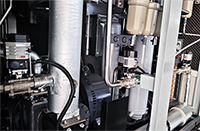



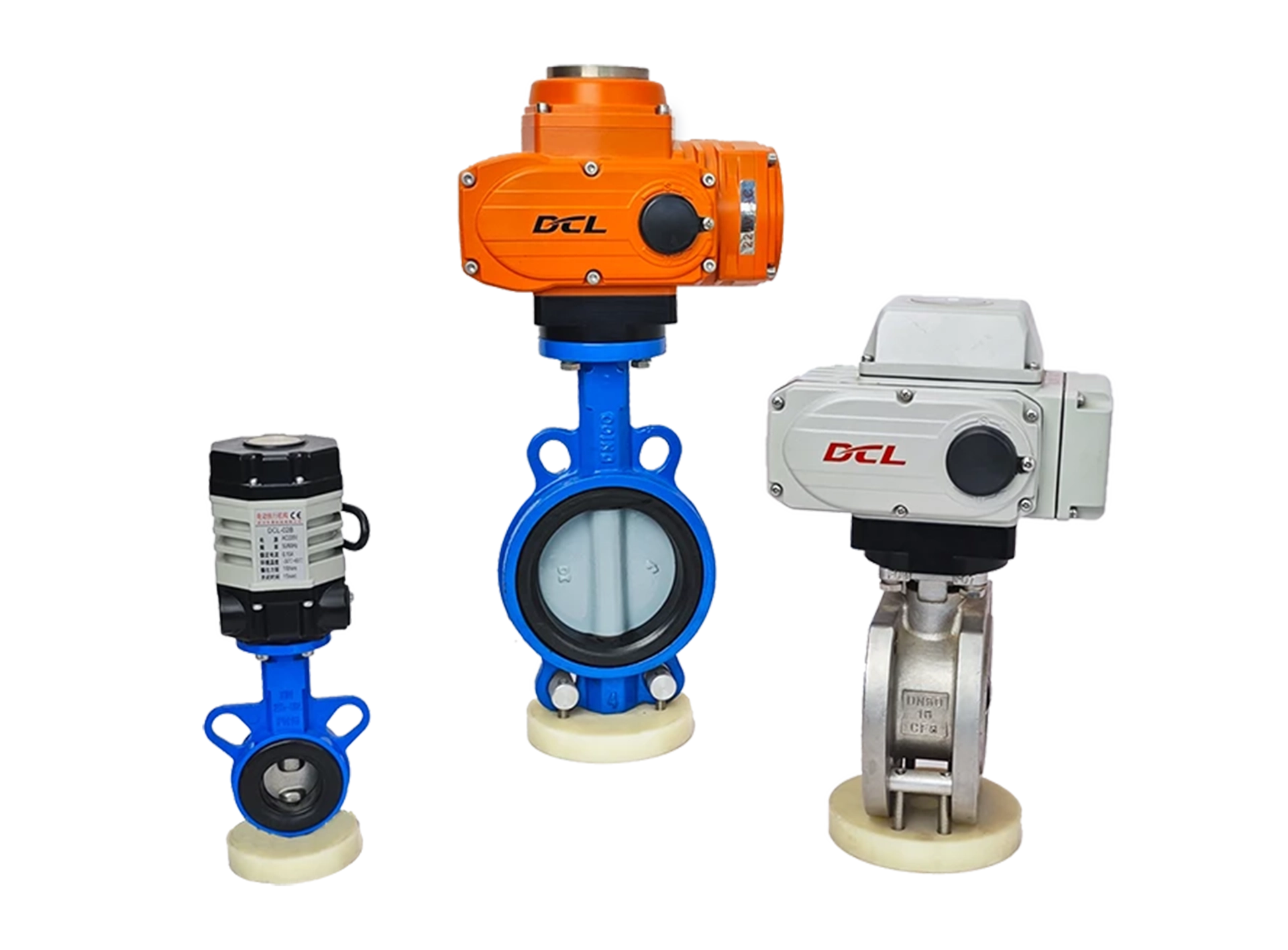
Ultra Small Actuator
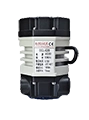
DCL-02
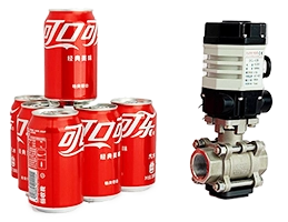
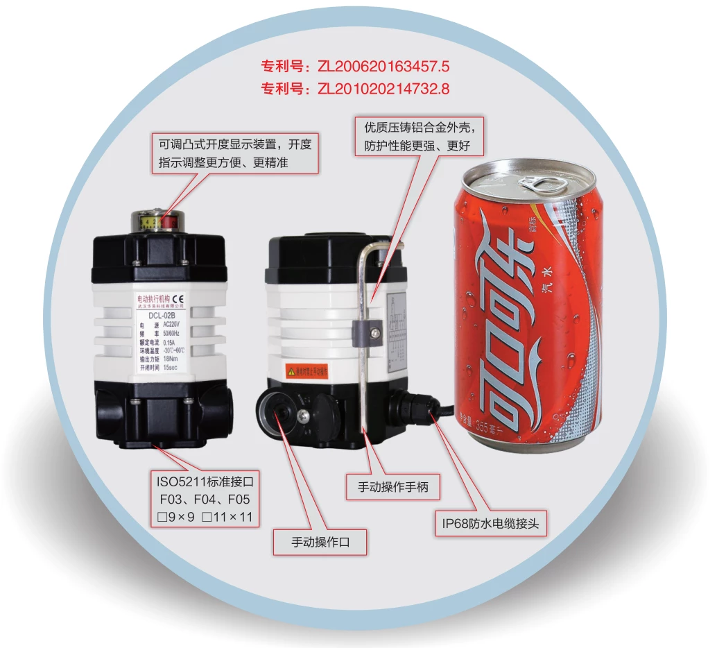
- Small size same as a cola can
- High-strength aluminum alloy shell for strong protection.
- High EMI performance.
Bewegungsrichtung
Teildrehung
Dämpfer
0 - 270°
Drehmoment/Betriebszeit
9~18Nm
7~60S
Art der Tätigkeit
Modulieren
Ein - Aus
Versorgungsspannung
24 V DC
AC110V
AC220V
Eingangs-/Ausgangssignal
4 - 20 mA
0 - 10 V
E/A-Schnittstelle
Zusätzliche Optionen
Entfeuchtung
Art der Tätigkeit
Modulieren
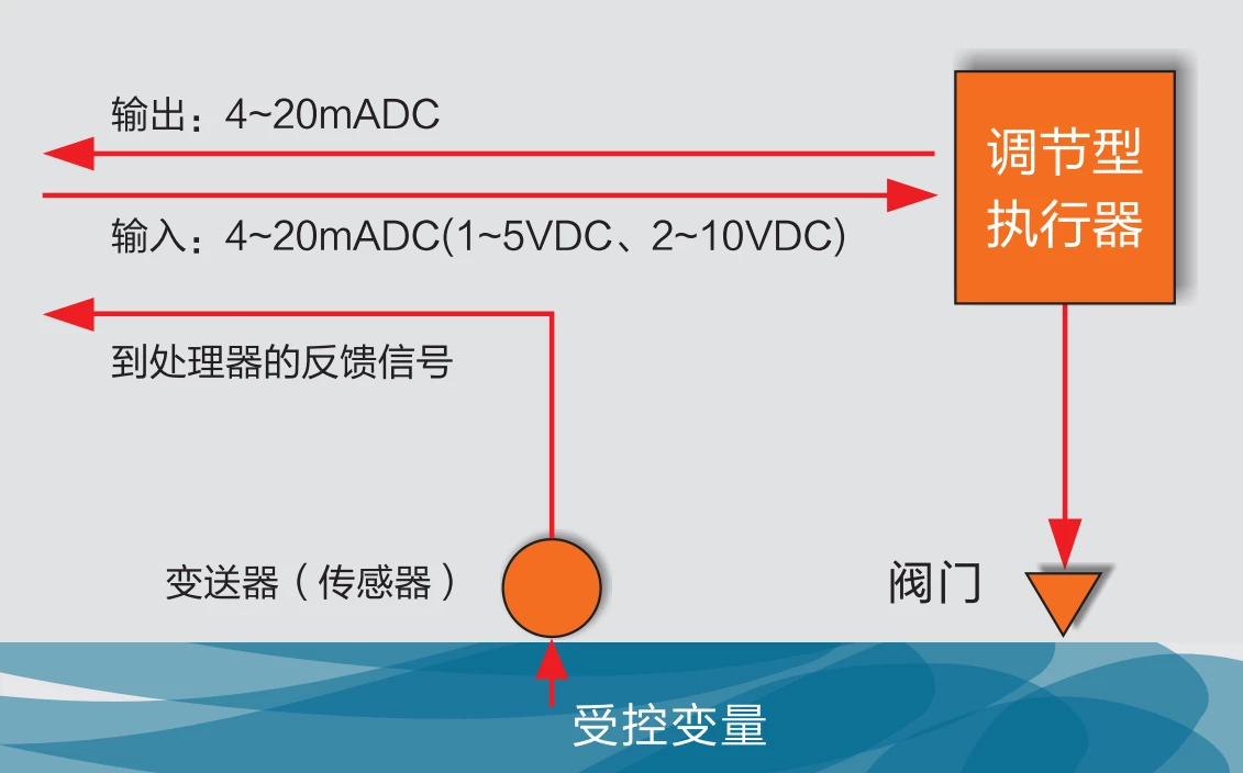
Der Aktor liest den Sollpositionswert vom Steuerungssystem über 4-20mA, 2-10V oder Feldbus wie Modbus, Ethernet usw. ab.
Anschließend fährt der Aktor das Ventil mithilfe eines internen Regelalgorithmus in die Zielposition.
Der Aktor gibt stets die Ventilposition in Echtzeit aus. 4-20mA, 2-10V oder Feldbus.
Im Betriebsmodus S4 kann der Aktor 1200 Mal pro Stunde starten.
Ein - Aus
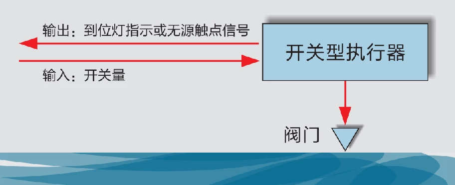
Der Aktor liest die Öffnungs- oder Schließanforderung vom Steuerungssystem über eine E/A-Schnittstelle, wie z. B. ein passives Signal oder ein aktives 24VDC/220VAC-Signal.
Anschließend fährt der Stellantrieb das Ventil in die Endposition OFFEN oder GESCHLOSSEN, je nach erforderlichem Eingangssignal.
Der Aktor gibt ein Rückmeldesignal OPEN oder CLOSE aus, sobald die Endposition erreicht ist.
Im Betriebsmodus S2 kann der Stellantrieb das Ventil 15 Minuten lang kontinuierlich betätigen.
Merkmale
Motor mit Übertemperaturschutz
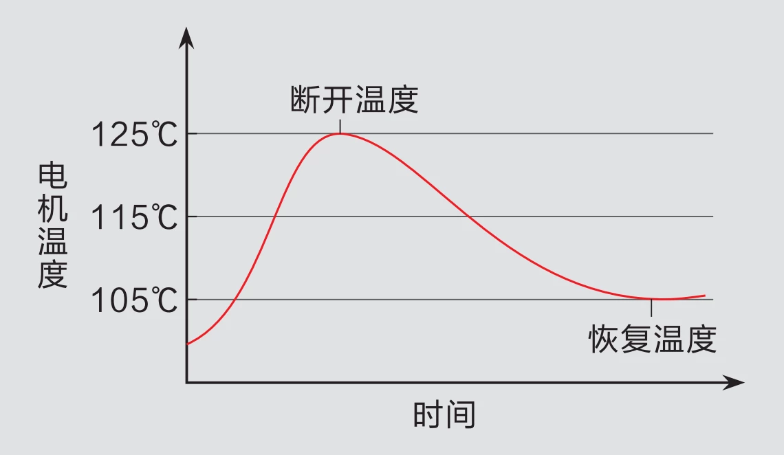
DCL hat den Motor speziell auf die Anforderungen des Aktuators abgestimmt, sodass der Motor im DCL-Aktuator ein hohes Anlaufdrehmoment liefert und gleichzeitig einen hohen Wirkungsgrad in der Anlaufphase beibehält, um den Temperaturanstieg so gering wie möglich zu halten. Der Motor besitzt ein geringes Trägheitsmoment, um eine hohe Modulationsgenauigkeit zu gewährleisten.
Im Motor ist eine Übertemperaturschutzvorrichtung eingebaut, die die Stromzufuhr unterbricht, wenn die Motortemperatur die zulässige Temperatur überschreitet (105℃/85℃, je nach Anwendungsszenario wählbar), und die Stromzufuhr wiederherstellt, wenn die Temperatur wieder unter die normale Temperatur gesunken ist.
Doppelpositionsbegrenzer
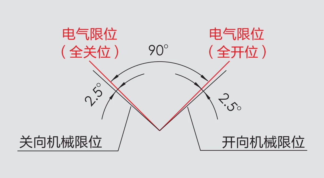
Es gibt zwei Positionsbegrenzungsvorrichtungen, die das Ventil vor Beschädigungen durch Betrieb über den Schwenkwinkel hinaus schützen.
An den Endpositionen „ÖFFNEN“ und „GESCHLOSSEN“ sind elektrische Endschalter angebracht. Sobald die Endposition erreicht ist, wird die Stromzufuhr zum Motor unterbrochen, um den Ventilantrieb zu stoppen.
Zusätzlich sind zwei mechanische Begrenzer an der Abtriebswelle angebracht, um das Ventil vor Überschwingen zu schützen. Im Normalbetrieb greifen die mechanischen Begrenzer nicht, da der elektrische Endschalter vorgeschaltet ist und auslöst, bevor die Abtriebswelle die mechanische Endposition erreicht.
Technical Parameters
| Power Supply | DC24V, AC24V, AC110V, AC220V |
| Standard Torque/Time | 18Nm/15S |
| Optional Torque/Time | 9Nm/7S, 18Nm/60S |
| Rotation Angle Range | 0~90° |
| Motor Power/Current | DC24V:8W / 0.7A AC24V:6W / 1.3A AC110V: 6W / 0.3A AC220V:6W / 0.15A |
| Control Circuit | DC24V: E-type/G-type |
| Weight | 1.2kg |
| Insulation Resistance | DC24V/AC24V:100MΩ/250VDC AC110V/AC220V:100MΩ/500VDC |
| Withstand Voltage | DC24V/AC24V: 500VAC for 1 minute |
| Water Proof Level | IP67 |
| Installation orientation | 360 ° installation at any angle |
| Electrical Interface | 7-core cable connection |
| Working Temperature | -25℃ ~ +55℃ |
| Selection of fuses | DC24V:2A AC24V:3A AC110V/AC220V:1A |
| DCL-02 Adjustable Control Parameters | |
| Eingangssignal | 4~20mA, 0~10V arbitrary calibration |
| output Signal | 4~20mA, 0~10V arbitrary calibration |
| Bus | 485/Modbus/CAN |
| Internet of Things | WIFI/LoRA/4G |
| Basic Error | ≤±1% |
| Check back | ≤1% |
| Hysteresis | Adaptive Hysteresis, customized |
| Reposition Times | 0 times |
| Repeatability Error | ≤1% |
Dimensions
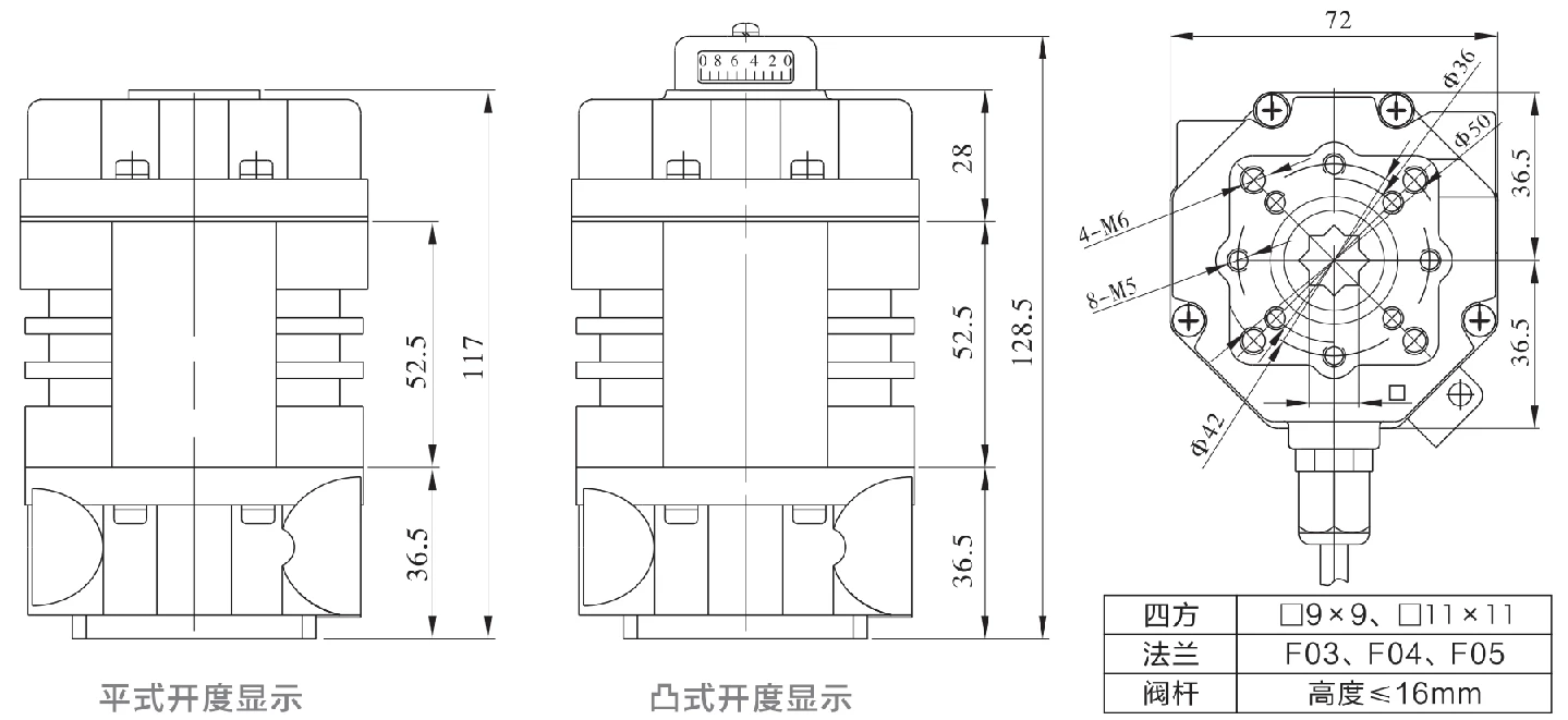
Application Circuit
Modulieren
E - Modulating with a control unit
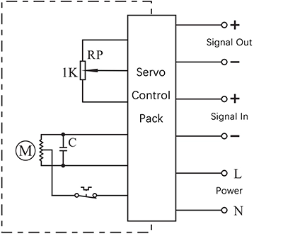
- Input: 4~20mA / 0~10V
- Output: 4~20mA / 0~10V
Connecting Details:
- Connecting AC85-220V supply power line to L and neutral to N.
- Connecting 4-20mA/2-10V input signal source from control system to input-/+.
- Connecting Output -/+ to the system to send out the real-time valve position.
Ein - Aus
A - With 2 active end-position signal outputs
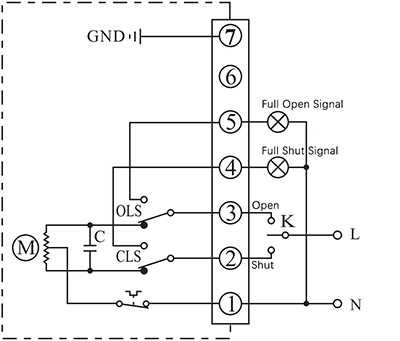
- Control actuator to open or close with K
- The output terminal of end-position OPEN/CLOSE will send out the event as a 220VAC active signal form when the end-position was reached.
Connecting Details:
- Connecting AC85-220V supply power neutral to P1.
- Switch AC85-220V line to CLOSE(P2) to close the valve
- Switch AC85-220V line to OPEN(P3) to open the valve.
- P5 is end-position OPEN terminal which will output a AC220V source which can be used to drive an Indication light when actuator reached end-position of open.
- P6 is end-position OPEN terminal which will output a AC220V source which can be used to drive an Indication light when actuator reached end-position of close.
- Connect earth to P7.
B - With 2 passive end-position switche
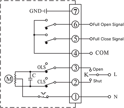
- Control actuator to open or close with K
- The output terminal of end-position OPEN/CLOSE will send out the event as a passive signal form when the end-position was reached.
Connecting Details:
- Connecting AC85-220V supply power neutral to P1.
- Switch AC85-220V line to CLOSE(P2) to close the valve
- Switch AC85-220V line to OPEN(P3) to open the valve.
- P4 is the COM for passive contact signal of end-position OPEN/CLOSE which is normally connected to signal GND.
- P5 is end-position OPEN terminal which will be connected to COM when actuator reached end-position of open.
- P6 is end-position CLOSE terminal which will be connected to COM when actuator reached end-position of close.
- Connect earth to P7.
G - DC motor with 2 end-position switches
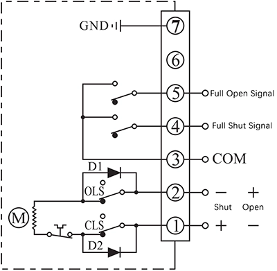
- Control actuator to open or close by the supply power direction between the terminal 1 and 2
- The output terminal of end-position OPEN/CLOSE will send out the event as a passive signal form when the end-position was reached.
Connecting Details:
- Connecting DC24V+ to P1 and DC24V- to P2 to close the valve.
- Connecting DC24V+ to P2 and DC24V- to P1 to close the valve.
- P3 is the COM for passive contact signal of end-position OPEN/CLOSE which is normally connected to signal GND.
- P4 is end-position OPEN terminal which will be connected to COM when actuator reached end-position of open.
- P5 is end-position CLOSE terminal which will be connected to COM when actuator reached end-position of close.
- Connect earth to P7.
Note:
- The circuit inside the dashed box is the internal circuit of actuator. While the circuit outside is a demonstration of electrical connection for using actuator.
- If you have other specific requirements about connecting circuit, please feel free to contact our technical support.


 English (UK)
  香港中文
香港中文  繁體中文
繁體中文  English (Canada)
  English (South Africa)
  English (Australia)
  English (New Zealand)
  English
  Español de Puerto Rico
  Français du Canada
  Español de México
  Español de Chile
  Español de Colombia
  Español de Uruguay
  עִבְרִית
  Nederlands (België)
  Français de Belgique
  Eesti
Eesti  Latviešu valoda
  Lietuvių kalba
  Français
  Deutsch
  Norsk nynorsk
  Deutsch (Österreich)
  Slovenčina
  Deutsch (Schweiz)
  Italiano