








7. 測試方法
7.1 測試條件
7.1.1 環境條件
7.1.1.1 參考大氣條件
執行器的參考性能應在以下大氣條件下進行測試:
環境溫度:20°C ± 2°C;
相對濕度:60% 至 70%;
大氣壓力:86 kPa 至 106 kPa。
7.1.1.2 一般大氣條件
當測試不在參考大氣條件下進行時,建議在以下大氣條件下進行測試:
環境溫度:15°C 至 35°C;
相對濕度:45% 至 75%;
大氣壓力:86 kPa 至 106 kPa。
7.1.1.3 其他環境條件
除了地球磁場之外,其他外部磁場和機械振動可以忽略。
7.1.2 電源條件
7.1.2.1 名義值
如 4.2.2 所述。
7.1.2.2 公差
測試條件的容差範圍如下:
額定電壓:±1%;
額定頻率:±1%;
諧波含量:小於 5%。
7.2 一般測試規定
7.2.1 測試產品應處於正常安裝位置。可連接電源並預熱1小時,使測試產品的內部溫度穩定。
7.2.2 測試前可以調整被測產品的零位。除非另有規定,測試過程中不得進行任何調整。
7.2.3 除非另有規定,因此被測產品和相關測試設備應在參考工作條件下穩定後再進行測量,並且應觀察並記錄所有可能影響測量結果的工作條件。
7.2.4 測試報告中應註明測試中所用標準儀器的精度,且其基本誤差限值應小於或等於被測產品基本誤差限值的三分之一。儀器的量程應與測量值的範圍相符。
7.2.5 測試過程中,電流輸入訊號應緩慢增加或減少,並沿同一方向接近測試點,確保無過衝。增加訊號應視為正向行程,減少訊號應視為反向行程。
7.2.6 除非另有規定,執行器的輸出軸(桿)在測試期間應承受額定負載。當載荷的作用方向與輸出軸(桿)的運動方向一致時,此載荷為正;否則,此載荷為負。
7.2.7 除非另有規定,否則測試測量點應位於輸入範圍的 0%、25%、50%、75% 和 100% 處。每個測試點應在訊號遞增和遞減方向上分別測量三次。出廠檢驗允許每個測試點測量一次。
7.2.8 除非另有規定,否則試驗的影響因素只能在規定的工作條件下改變。所有其他工作條件應在參考條件下保持不變。
7.2.9 如果由於條件原因無法在參考大氣條件下進行影響因子試驗,則可以在一般大氣條件下進行試驗。
7.2.10 除非另有規定,否則測試的額定行程範圍如下:
多圈:10圈;
角度行程:90°;
線性行程:16 毫米。
7.3 基本錯誤
基本誤差的計算方法是:緩慢增加或減少輸入訊號,記錄輸入訊號值和輸出軸(桿)在正向和反向行程方向上的行程值,依照公式(1)計算。

方程式(1)
在哪裡:
δ:基本誤差,%;
L1:輸出軸(桿)的行程值,以度(°)、毫米(mm)或圈數(r)表示;
Lo:輸出軸(桿)的理論行程值,以度(°)、毫米(mm)或圈數(r)表示;
L:輸出軸(桿)的額定行程範圍,以度(°)、毫米(mm)或圈數(r)表示。
檢查每個測量點的基本誤差是否超過 6.1.1 中規定的限值。
7.4 位置輸出訊號基本偏差
將位置輸出訊號連接至 250Ω 負載阻抗,並將執行器運轉至「全閉」位置。將位置輸出訊號調整至 4mA;將執行器運轉至「全開」位置,並將位置輸出訊號調整至 20mA。然後,運行執行器並記錄正反向行程中各點的位置輸出訊號值。基本偏差根據公式 (2) 計算。

公式(2)
在哪裡:
△0:位置輸出訊號基本偏差,%;
Io:位置輸出訊號的理論值,單位為毫安培(mA);
I1:位置輸出訊號的測量值,單位為毫安培(mA);
I:位置輸出訊號的範圍,單位為毫安培 (mA)。 (4 mA 至 20 mA 時,I = 16 mA;0 mA 至 20 mA 時,I = 20 mA)。
檢查每個測量點的基本偏差是否超過 6.1.2 中規定的限值。
7.5 滯後
執行器的滯後性由在每個測試點測量的正向和反向行程基本誤差之間的最大代數差決定,如 7.3 和 7.4 所述。
7.6 死區
對於調節執行器,應在額定行程的 25%、50% 和 75% 處測量死區。測量步驟如下:
緩慢增加(或減少)輸入訊號,直到輸出軸(桿)出現可察覺的行程變化,並記錄此時的輸入訊號值 I (mA);
然後緩慢地向相反方向減小(或增大)輸入訊號,直到輸出軸(桿)發生明顯的行程變化,並記錄輸入訊號值 I² (mA)。
死區依公式(3)計算。

公式(3)
在哪裡:
△:死區,%。
7.7 時間延遲
將輸入範圍為 15% 的階躍訊號施加到調節執行器的輸入訊號端,使用示波器記錄輸入訊號曲線和位置輸出訊號曲線,觀察從初始輸入訊號到輸出訊號開始變化的時間差,看是否超過 6.1.5 中規定的限值。
7.8 額定擊球時間誤差
在致動器上施加額定負載的 45% 至 55%,施加足以使致動器輸出軸(桿)移動額定行程的階躍訊號,並記錄輸出軸(桿)移動額定行程所需的時間。額定行程時間誤差依公式(4)計算。

公式(4)
在哪裡:
δt:額定衝程時間誤差,%;
t1:輸出軸(桿)移動額定行程所需的測量時間,以秒(s)為單位;
t:理論額定衝程時間,以秒(s)為單位。
7.9 起始特徵
在執行器的輸出軸(桿)上施加反向額定負載,並將電源電壓調至下限值。然後施加輸入訊號,觀察執行器是否能正常啟動。
7.10 行程控制機構重複性誤差
對於具有行程控制機構的執行器,在輸出軸(桿)上施加額定負載的 25% 至 30%,並交替進行正向和反向行程操作五次。觀察並記錄行程控制機構切換時輸出軸(桿)的行程值。計算每個記錄值與基準值之間的誤差,並確定該誤差是否超過 6.1.8 中規定的限值。
7.11 絕緣電阻
在一般大氣條件下,且執行器處於卸載狀態時,斷開被測產品的電源,並將電源開關保持在「開」的位置。將輸入端子和電源端子短路,然後使用 500V 直流絕緣電阻測試器測量端子之間的絕緣電阻,測量方法請參閱 6.1.9 節。
7.12 絕緣強度
在一般大氣條件下,且執行器處於卸載狀態時,請斷開電源並將電源開關保持在「開」的位置。將輸入端和電源端短路,然後根據6.1.10中規定的電壓和頻率,將測試電壓從零緩慢升至規定值並保持1分鐘。觀察是否有擊穿或電弧現象,然後緩慢將測試電壓降至零並斷開測試電源。
7.13 溫度上升
試驗前,使用電橋測量馬達和電力變壓器繞組的冷態電阻,然後依照7.14節規定連續運轉12小時,並立即測量馬達和電力變壓器繞組的熱態電阻。根據公式(5)計算溫升。

公式(5)
在哪裡:
問:溫度上升值,單位為攝氏度(°C);
R₂:繞組的熱電阻,單位為歐姆(Ω);
R₁:繞組的冷態電阻,單位為歐姆(Ω);
T1:測量冷電阻時的室溫,單位為攝氏度(°C);
T₂:耐熱期間的室溫
7.14 長期運轉穩定性
在額定行程範圍內操作執行器,並施加額定負載的 30%,佔空比為 20% 至 80%。依照 4.2.6 的要求進行 48 小時的運行,並記錄每小時的循環次數。測試結束後,驗證執行器是否符合 6.1.12 的要求。
7.15 最大和最小控制扭矩和推力重複性誤差
測試步驟如下:a) 將致動器安裝在試驗台上,將開啟和關閉方向的扭力保護值皆設定為最大控制扭力或推力值,並逐漸載入致動器直至觸發「扭力過載」或「推力過載」警報。測量輸出扭力或推力值。每個方向測量三次,取平均值作為輸出扭力或推力的基準值。 b) 將致動器安裝在試驗台上,將開啟和關閉方向的扭力保護值皆設定為最小控制扭力或推力值,並逐漸載入致動器直到觸發「扭力過載」或「推力過載」警報。測量輸出扭力或推力值。每個方向測量三次,取平均值作為輸出扭力或推力的基準值。 c) 根據公式(6)計算控制扭力或推力的重複性誤差。

第六方程式:
在這個公式中:
δ0:% 中控制扭力或推力的重複性誤差
Ms:測量的輸出扭力或推力值,單位為 N·m(或推力,單位為 N)
Mz:輸出扭力或推力的基準值,單位為 N·m(或推力,單位為 N)。
7.16 手動-電動開關機構
測試步驟如下:a) 空載開關檢查。將執行器從電動模式切換到手動模式,轉動手輪使輸出軸順時針和逆時針各旋轉至少一整圈;然後,用電動方式操作執行器,使輸出軸雙向各旋轉至少一整圈。重複兩次,確認是否符合 6.1.14 的要求。 b) 負載開關檢查。將執行器安裝在試驗台上,將開啟和關閉方向的保護扭力調整至最大控制扭矩,並逐漸增加致動器的負載,直到扭矩開關動作。停止載入後,無需卸載,重複 a) 部分的測試,確認是否符合 6.1.14 的要求。
7.17 智能功能
7.17.1 顯示功能
透過人機介面檢查工作參數、運作狀態資訊、故障警報等顯示訊息是否正常,顯示內容是否完整清晰。
7.17.2 參數設定功能
在不打開電氣蓋的情況下,檢查人機介面是否允許設定行程、扭力、電流輸入訊號校準和輸出訊號調整等參數。
7.17.3 現場配置功能
無需打開電氣蓋,透過人機介面將執行器的四路開關接點輸出設定為:開位閉合、開位斷開、閉合、閉合斷開。啟動執行器至開位和閉合位置,檢查開關接點輸出是否符合設定要求。
如果適用,檢查斷電後的運作情況,並調整扭力保護等參數。
7.17.4 故障自診斷與警報功能
在空載條件下,給執行器通電,斷開執行器控制系統的馬達溫度線,檢查馬達過熱警報是否觸發。
7.17.5 功率序列自適應功能
對於使用三相電源的執行器,改變電源的相序,並確認在本地控制和遠端控制模式下切換方向是否正確。
7.17.6 連續輸出扭力(推力)測量功能
將執行器放置在測試台上,並在運作過程中不斷改變施加的扭力(推力),觀察人機介面上顯示的扭力(推力)值是否會相應變化。
7.18 噪音
在門窗緊閉、背景噪音不超過 45 分貝的房間內,對致動器進行空載啟動,並在距離執行器表面 1 公尺處測量噪音。確認噪音符合 6.1.16 中的要求。
7.19 無段(變頻)調速
設定執行器在到達目標位置時減速,並在不同的負載條件下測試速度是否在規定的範圍內變化,以確認其符合要求。
7.20 環境溫度影響
在空載條件下,應將執行器置於溫度測試箱中。測試溫度和測試順序如下:
適用於工作環境溫度為-10°C至55°C的執行器:
20°C(參考值),40°C,55°C,20°C,0°C,-10°C,20°C;
For actuators with a working ambient temperature of -20°C to 60°C:
20°C (reference), 40°C, 60°C, 20°C, 0°C, -20°C, 20°C;
For actuators with a working ambient temperature of -30°C to 70°C:
20°C (reference), 45°C, 70°C, 20°C, 0°C, -30°C, 20°C.
If agreed upon by all parties, tests may be conducted at just four temperature points: 20°C (reference), the maximum temperature, the minimum temperature, and 20°C. The permissible tolerance at each temperature point is ±2°C. At each temperature point, the temperature should be maintained for 2 hours to allow the product’s internal components to reach thermal stability. At the full stroke’s 0% and 100% positions, the low-end and high-end values of the proportional control and position signal output should be measured. The average of three measurements at each temperature point should be taken. The changes in the low-end and high-end values at each temperature point, when the temperature changes by 10°C, should be calculated using formulas (7) and (8), and it should be confirmed that the results meet the requirements of section 6.2.1.


在哪裡:
△T0: The change in the low and high-end values of the position output signal when the temperature changes by 10°C, in %;
XTi: The measured low and high-end values of the position output signal at the adjacent temperature, in milliamps (mA);
XT0: The measured low and high-end values of the position output signal at the starting temperature, in milliamps (mA);
Ti: The adjacent temperature, in degrees Celsius (°C);
T0: The starting temperature, in degrees Celsius (°C);
△T1: The change in the low and high-end values of the output shaft (rod) when the temperature changes by 10°C, in %;
LTi: The measured low and high-end stroke values of the output shaft (rod) at the adjacent temperature, in degrees (°), millimeters (mm), or rotations (r);
LT0: The measured low and high-end stroke values of the output shaft (rod) at the starting temperature, in degrees (°), millimeters (mm), or rotations (r).
7.21 Humidity Impact
Place the actuator in a temperature and humidity chamber, raise the temperature to 40°C ± 2°C, and adjust the humidity to 91%–95%, maintaining it for 48 hours. After the test, check the actuator’s insulation resistance as specified.
7.22 Power Supply Voltage Influence
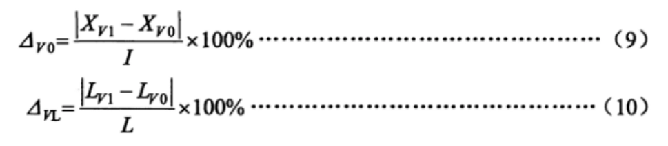
Under no-load conditions, the power supply voltage of the actuator is adjusted from the nominal value to both the upper and lower limit values. At the 0% and 100% positions of the full stroke, the low-end and high-end values of the proportional control and position signal outputs are measured. The average of three measurements at each point is taken, and the changes in the lower limit and range are calculated using formulas (9) and (10). The results should be verified to meet the requirements of section 6.2.3.
在哪裡:
△V0: The change in the low and high-end values of the position output signal when the power supply voltage changes, in %;
XV1: The measured low and high-end values of the position output signal at the upper and lower limit voltages, in milliamps (mA);
XV0: The measured low and high-end values of the position output signal at the nominal voltage, in milliamps (mA);
△VL: The change in the low and high-end values of the output shaft (rod) when the power supply voltage changes, in %;
LV1: The measured low and high-end stroke values of the output shaft (rod) at the upper and lower limit voltages, in degrees (°), millimeters (mm), or rotations (r);
LV0: The measured low and high-end stroke values of the output shaft (rod) at the nominal voltage, in degrees (°), millimeters (mm), or rotations (r).
7.23 Mechanical Vibration Influence
Under no-load conditions, the actuator is installed on a vibration test stand. The actuator is run to both the 0% and 100% positions of the full stroke. Sweep frequency vibration is applied at a frequency of 10Hz to 150Hz in three mutually perpendicular directions to identify the resonance point. If a resonance point is found, vibration tests are conducted at the resonance frequency for 30 minutes. If no resonance point is found, a 30-minute vibration test is conducted at a frequency of 150Hz.
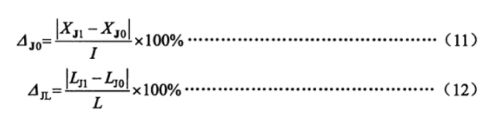
During the test, the low-end and high-end values of the actuator’s output are measured. The changes in the low-end and high-end values are calculated using formulas (11) and (12). The results should be verified to meet the requirements of section 6.2.4.
在哪裡:
△J0: The change in the low and high-end values of the position output signal due to mechanical vibration, in %;
XJ1: The measured low and high-end values of the position output signal during the vibration test, in milliamps (mA);
XJ0: The measured low and high-end values of the position output signal before the vibration test, in milliamps (mA);
△JL: The change in the low and high-end values of the output shaft (rod) due to mechanical vibration, in %;
LJ1: The measured low and high-end stroke values of the output shaft (rod) during the vibration test, in degrees (°), millimeters (mm), or rotations (r);
LJ0: The measured low and high-end stroke values of the output shaft (rod) before the vibration test, in degrees (°), millimeters (mm), or rotations (r).
7.24 Transportation Environmental Impact
Temperature, shock, and free-fall tests shall be performed according to the test parameters specified in section 6.2.5 of this standard and the methods in GB/T 25480. After the tests, the zero position can be adjusted, followed by performance testing and visual inspection.
Note: If the environmental temperature influence test has already been performed at 55°C (or higher), the high-temperature test can be waived.
7.25 Radio Frequency Electromagnetic Field Radiation Immunity
Under no-load conditions, the actuator is moved to the 50% position of the full stroke. A radiated electromagnetic field in the frequency range of 80 MHz to 1000 MHz with an intensity of 3V/m is applied at a distance of 3 meters from the actuator, in accordance with the requirements of GB/T 17626.3. During this test, the changes in position feedback output signal or output shaft (rod) stroke values are observed and recorded to confirm that the values meet the requirements of section 6.2.6 of this standard.
7.26 Electrical Fast Transient/Burst Immunity
Under no-load conditions, the actuator is moved to the 50% position of the full stroke. The test voltage is applied according to the requirements of GB/T 17626.4, with a positive and negative 1000V on the power supply terminal and a positive and negative 500V on the signal input terminal. During this test, the changes in position feedback output signal or output shaft (rod) stroke values are observed and recorded to confirm that the values meet the requirements of section 6.2.7 of this standard.
7.27 Surge (Impulse) Immunity
Under no-load conditions, the actuator is moved to the 50% position of the full stroke. A positive and negative 1kV voltage is applied between the actuator’s power supply line and ground, as per GB/T 17626.5. During this test, the changes in position feedback output signal or output shaft (rod) stroke values are observed and recorded to confirm that the values meet the requirements of section 6.2.8 of this standard.
7.28 靜電放電抗擾度
Under no-load conditions, the actuator is moved to the 50% position of the full stroke. The actuator’s shell is securely grounded. Positive and negative 4kV contact discharge and then positive and negative 8kV air discharge are applied to the actuator, following the requirements of GB/T 17626.2. During this test, the changes in position feedback output signal or output shaft (rod) stroke values are observed and recorded to confirm that the values meet the requirements of section 6.2.9 of this standard.
7.29 工頻磁場抗擾度
Under no-load conditions, the actuator is placed on the external magnetic field test stand and moved to the 50% position of the full stroke. The magnetic field strength is 400 A/m, and the test directions are X/Y/Z, in accordance with GB/T 17626.8. During this test, the changes in position feedback output signal or output shaft (rod) stroke values are observed and recorded to confirm that the values meet the requirements of section 6.2.10 of this standard.
7.30 外觀
Visual and tactile methods should be used to check whether the surface is flat and smooth, without cracks, burrs, or other defects that affect the appearance. The surface coating should be securely attached, flat, smooth, and uniform in color, with no oil stains, indentations, or other mechanical damage. For actuators with display functions, the display should be clearly visible without missing characters.
7.31 Enclosure Protection Level
The IP67 or IP65 enclosure protection test should be carried out according to the method specified in GB 4208—2008.
7.32 防爆性能
Explosion-proof tests should be conducted by a nationally recognized testing unit, according to the requirements of GB 3836.1 and GB 3836.2.


 English (UK)
  香港中文
香港中文  繁體中文
繁體中文