


DCL actuators support the Modbus-RTU protocol. Referring to this application manual, you can connect DCL actuators to Modbus.

Panel
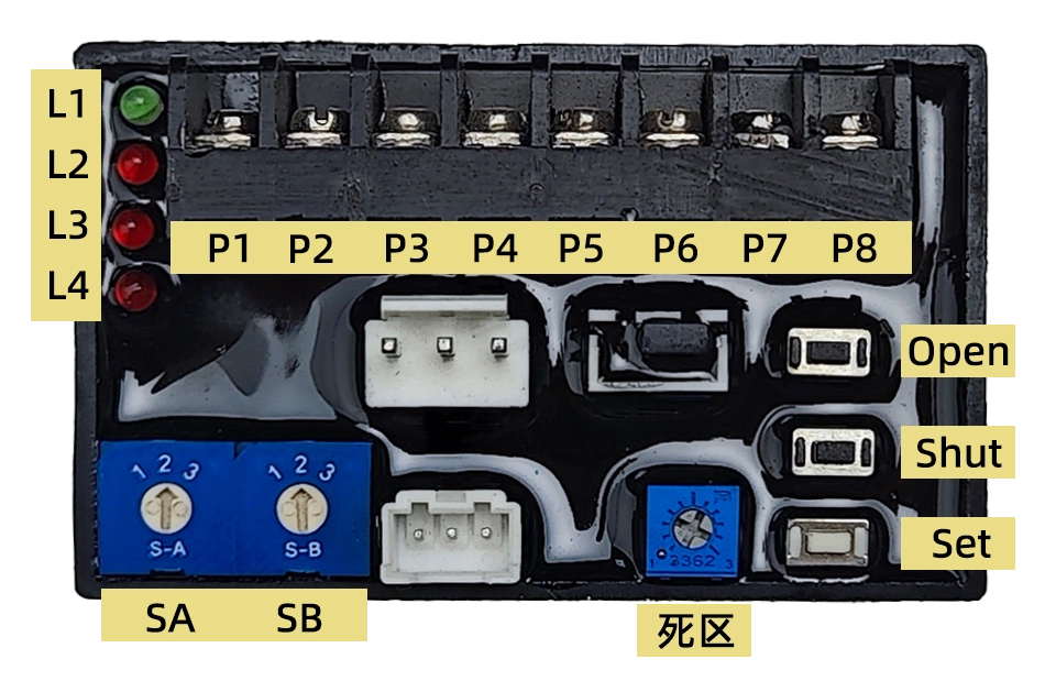
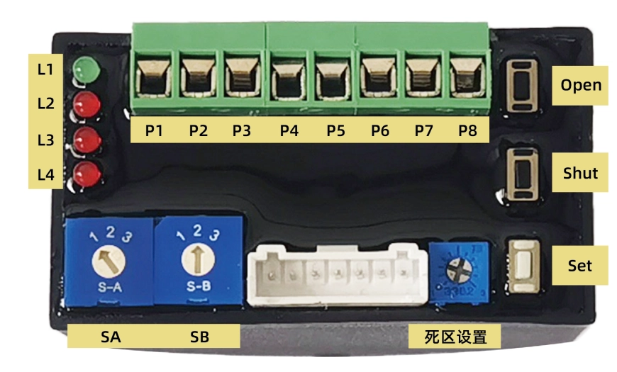
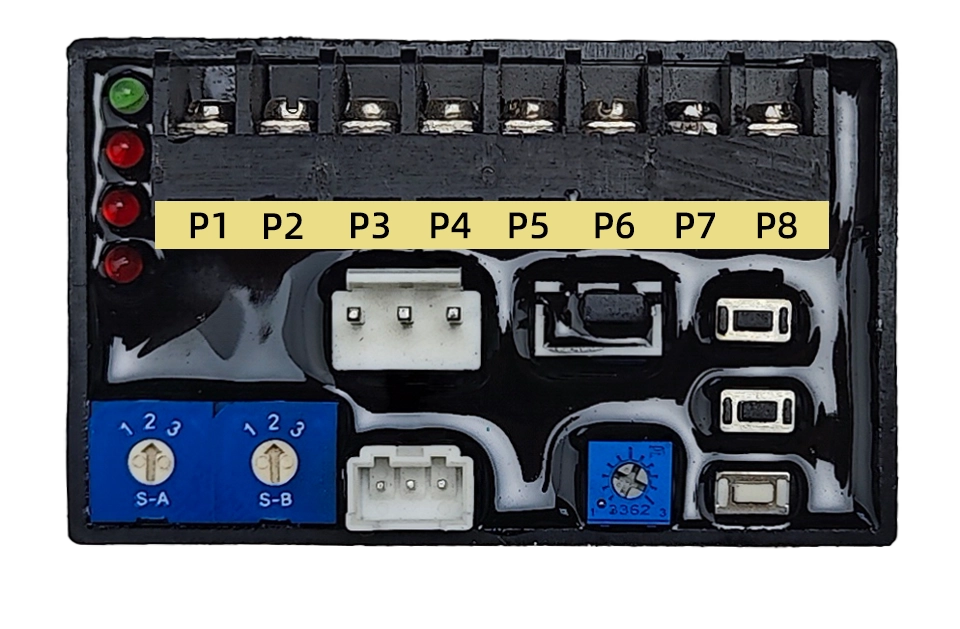
1. Interface Definition
P1:220VAC N
P2:220VAC L
P3:4-20mA Input –
P4:4-20mA Input+
P5:4-20mA Output-
P6:4-20mA Output+
P7:RS485 A
P8:RS485 B
2. Button
Open: Used in setting mode. Press this button to open the actuator while release it to stop. Press Set and Open simultaneously to set the full open position.
Shut: Used in setting mode. Press this button to Shut the actuator while release it to stop. Press Set and Open simultaneously to set the full shut position.
Set: Used in setting mode. Combination use this button with others to set the parameters.
3. Switch
SA: Set operation mode
1–Normal Modulation
2–Setting Mode
3–Reverse Modulation
SB: Set Safety Position (Default set to 2)
1–Drive to Fully Open
2–Keep Position
3–Drive to Fully Shut
4. Hystersis
Set a hysteresis value from 0.5% to 5% with one scale stands for 0.5%
The actuator will not change the valve position until the gap between the input signal indicated position and the current valve position become larger then the hysteresis value.
5. Indication
L1: Green, Power Indication;
L2: Red, Input signal error, turned on when input signal is over range;
L3: Red, Potentiometer error, turned on when potentiometer is abnormal or connection wire is broken;
L4: Red, Stuck error, turned on when actuator can not be driven to open or close.
Set up
Switch SA to 2 to enter the setting mode. Then you can set the operation rotation range, set the Safety position, calibrate the input and output signal and etc.
1. Set Operation Range
Set Fully Close Position:
- Press the KO/KC button to drive the valve to the fully closed position.
- Hold the KS button and then the KC button until L2 is turned on about 3-4 seconds later which means the fully closed position configuration is done.
- Now you can release these 2 buttons.
Set Fully Open Position:
- Press the KO/KC button to drive the valve to the fully open position.
- Hold the KS button and then the KO button until L2 is turned on about 3-4 seconds later which means the fully open position configuration is done.
- Now you can release these 2 buttons.
Note: When the fully open and close position was configured with the same position, the configuration will be done successfully. But the actuator will not rotate in modulation mode.
2. Set Modbus Parameters
- Registers from 0x0040 to 0x0042 are used to set communication parameters.
- First enter the setting mode by writing value 0xA501 to register 0x0040, Then set the slave ID and baud rate by writing values to registers 0x0041 and 0x0042.
- New parameters will be updated in 1S.
- Exit setting mode by writing 0x0000 to register 0x0040.
Start to Modulation
Turn SA to 1 to start modulation.
- After power-on, the actuator defaults to follow the 4-20mA input signal for modulation.
- Sending commands through modbus enables the actuator to work in communication control mode and automatically return to analog control mode after the actuator is powered off and on again.
Modulation with 4-20mA
- The actuator will drive the valve to the specific position as the 4-20mA input signal stands for.
- The 4-20mA output signal will output the valve position in real time.
- The “ON/OFF Output Open” will output an effective signal(connect to COM) when the valve was driven to the fully open position.
- The “ON/OFF Output Shut” will output an effective signal(connect to COM) when the valve was driven to the fully close position.
- The actuator will drive the valve to the Safety position when supply power was broken down or input signal is fault.
- The actuator will return to modulation mode after supply power and input signal is recovered.
Note: You can turn SW2 to 3 to activate the reverse operation. In which, 4mA input value will be transferred as 20mA, and 20mA will be transferred as 4mA. So the modulation is just like reversed.
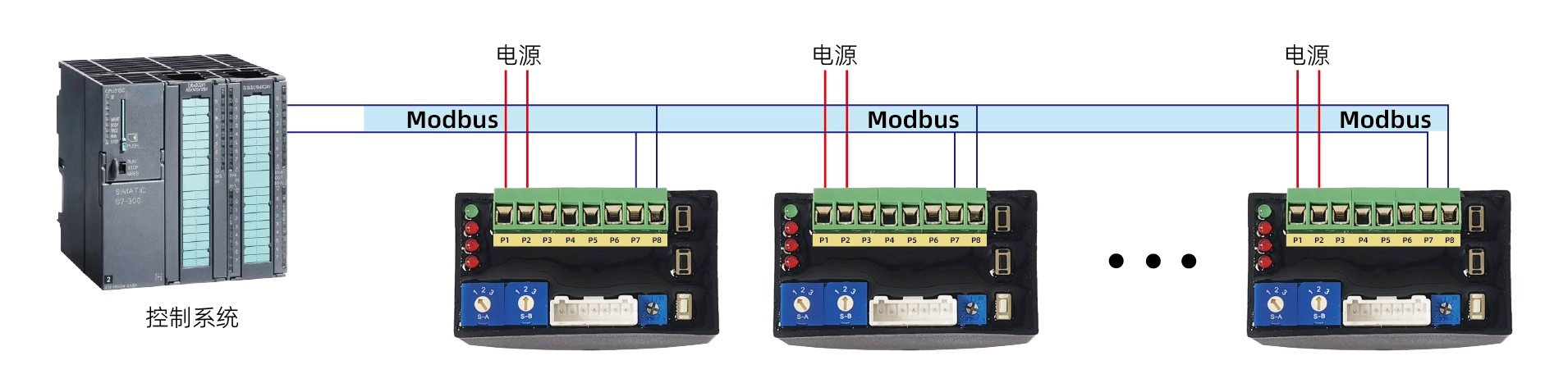
Modulation with Modbus-RTU/RS485
Hardware Layer
- DCL actuator support Modbus-RTU Protocol,RS485 is used in physical layer。
- Slave ID: Default to 1
- Baud Rate:Configurable with default value 9600
- RS485 Data Format:1 start bit + 8 data bit + 1 stop bit (no parity check)
1. Interface
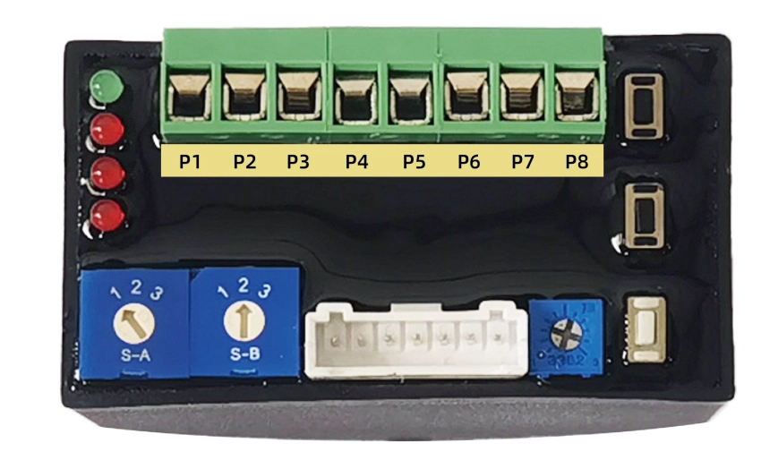
P1:Power supply –
P2:Power supply+
P7:RS485 A
P8:RS485 B
P3~P6:Reserved(4~20mA/0~10V)
2. Connection Diagram
Application Layer
1、ADU
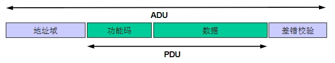
2. Function Codes
| ID | name | describe |
|---|---|---|
| 0x03 | Read multiple registers | In a remote device, use this function code to read the contents of consecutive blocks in the hold register |
| 0x06 | Write a single register | In a remote device, use this function code to write a single register |
| 0x10 | Write multiple registers | In a remote device, use this function code to write consecutive register blocks (1 to approximately 120 registers) |
3. Set Communication Parameters
- Registers from 0x0040 to 0x0042 are used to set communication parameters.
- First enter the setting mode by writing value 0xA501 to register 0x0040, Then set the slave ID and baud rate by writing values to registers 0x0041 and 0x0042.
- New parameters will be updated in 1S.
- Exit setting mode by writing 0x0000 to register 0x0040.
4. Reset Communication Parameters to Default Value
- Set SA and SB to 2.
- Hold KS more then 3 seconds, the red led will blink, now release KS.
- Then hold KC more then 3 seconds, the red led will blink again, release KC.
- Now the communication parameters will be reset to default value (slave ID to 1,baud rate to 9600).
This is used when the communication parameters are missed.
5、Register List
| Register address | Register bit | Signal group | Signal name | minimum value | Maximum value | Company | Read/Write | type | Truth table | describe |
|---|---|---|---|---|---|---|---|---|---|---|
| 0x0010 | b15-b5 | \ | \ | \ | \ | \ | r/w | hex | Keep 0 | retain |
| b5 | \ | \ | \ | \ | \ | r/w | hex | Keep 0 | retain | |
| b4 | control | stop | \ | \ | \ | r/w | hex | 1: Stop, 0: Normal | Stop running | |
| b3 | \ | \ | \ | \ | \ | r | hex | Keep 0 | retain | |
| b2 | \ | \ | \ | \ | \ | r | hex | Keep 0 | retain | |
| b1-b0 | control | mode | \ | \ | \ | r/w | hex | 1: Communication control | control Model | |
| 0x0011 | b15-b0 | control | SetOpenDegree | 0 | 10000 | % | r/w | int/hex | 0-10000 corresponds to 0-100% opening | Control the opening of the valve (ratio coefficient 1/100) |
| 0x0012 | b15-b0 | \ | \ | \ | \ | \ | r | hex | Keep 0 | retain |
| 0x0013 | b15-b0 | \ | \ | \ | \ | \ | r | hex | Keep 0 | retain |
| 0x0014 | b15-b0 | \ | \ | \ | \ | \ | r | hex | Keep 0 | retain |
| 0x0015 | b15-b0 | \ | \ | \ | \ | \ | r | hex | Keep 0 | retain |
| 0x0016 | b15-b0 | \ | \ | \ | \ | \ | r | hex | Keep 0 | retain |
| 0x0017 | b15-b0 | \ | \ | \ | \ | \ | r | hex | Keep 0 | retain |
| 0x0018 | b15-b6 | \ | \ | \ | \ | \ | r | hex | Keep 0 | retain |
| b5 | infor | errPosition | \ | \ | \ | r | hex | 1: Position signal malfunction | Position signal fault sign | |
| b4 | infor | errSignal | \ | \ | \ | r | hex | 1: Input Signal malfunction | Input Signal fault flag | |
| b3 | infor | overTorqueFlag | \ | \ | \ | r | hex | 1: Overload | Overload Flag | |
| b2 | infor | stuckFlag | \ | \ | \ | r | hex | 1: Blocked rotation | Blockage sign | |
| b1 | infor | openRunFlag | \ | \ | \ | r | hex | 1: Closing the valve | Valve opening sign | |
| b0 | infor | closeRunFlag | \ | \ | \ | r | hex | 1: Opening the valve | Valve closing sign | |
| 0x0019 | b15-b0 | infor | openDegree | 0 | 10000 | % | r | int/hex | 0-10000 corresponds to 0-100% opening | Current valve opening (ratio coefficient 1/100) |
| 0x001A | b15-b0 | \ | \ | \ | \ | \ | r | hex | Keep 0 | retain |
| 0x001B | b15-b0 | \ | \ | \ | \ | \ | r | hex | Keep 0 | retain |
| 0x001C | b15-b0 | \ | \ | \ | \ | \ | r | hex | Keep 0 | retain |
| 0x001D | b15-b0 | \ | \ | \ | \ | \ | r | hex | Keep 0 | retain |
| 0x001E | b15-b0 | \ | \ | \ | \ | \ | r | hex | Keep 0 | retain |
| 0x001F | b15-b0 | \ | \ | \ | \ | \ | r | hex | Keep 0 | retain |
| 0x0040 | b15-b0 | config | cfgMode | 1 | 127 | \ | rw | hex | 0x0000: Enter normal mode | Mode selection, configuration parameters can only be modified in configuration mode |
| 0x0041 | b15-b0 | config | cmm_addr | 1 | 127 | \ | rw | hex | 1~127 | Set communication address |
| 0x0042 | b15-b0 | config | cmm_baudrate | \ | \ | \ | rw | hex | 0: Baud rate 4800 | set baud rate |
| 0x0043 | b15-b0 | \ | \ | \ | \ | \ | r | hex | Keep 0 | retain |
| 0x0044 | b15-b0 | \ | \ | \ | \ | \ | r | hex | Keep 0 | retain |
| 0x0045 | b15-b0 | \ | \ | \ | \ | \ | r | hex | Keep 0 | retain |
| 0x0046 | b15-b0 | \ | \ | \ | \ | \ | r | hex | Keep 0 | retain |
| 0x0047 | b15-b0 | \ | \ | \ | \ | \ | r | hex | Keep 0 | retain |
| 0x0048 | b15-b0 | \ | \ | \ | \ | \ | r | hex | Keep 0 | retain |
Demo Communication Data
1. Set Position
Enter Modbus Control Mode:
Tx→◇01 10 00 10 00 01 02 00 01 65 00
Rx←◆01 10 00 10 00 01 00 0C
Set Position: 0%
Tx→◇01 10 00 11 00 01 02 00 00 A5 11
Rx←◆01 10 00 11 00 01 51 CC
Set Position: 50% (5000 -> 0x1388)
Tx→◇01 10 00 11 00 01 02 13 88 A8 47
Rx←◆01 10 00 11 00 01 51 CC
Set Position: 100% (10000 -> 0x2710)
Tx→◇01 10 00 11 00 01 02 27 10 BF 2D
Rx←◆01 10 00 11 00 01 51 CC
Stop
Tx→◇01 10 00 10 00 01 02 00 11 64 CC
Rx←◆01 10 00 10 00 01 00 0C
2. Get Position
Tx→◇01 03 00 18 00 02 44 0C
Rx←◆01 03 04 00 30 00 00 FA 3C
3. Set Modbus Slave ID
Enter Setting Mode
Tx→◇01 10 00 40 00 01 02 A5 01 12 00
Rx←◆01 10 00 40 00 01 00 1D
Set Slave ID to 2
Tx→◇01 10 00 41 00 01 02 00 02 28 80
Rx←◆01 10 00 41 00 01 51 DD
Exit Setting Mode
Tx→◇02 10 00 40 00 01 02 A5 00 C7 30
Rx←◆02 10 00 40 00 01 00 2E
4. Set Modbus Baud Rate
Enter Setting Mode
Tx→◇01 10 00 40 00 01 02 A5 01 12 00
Rx←◆01 10 00 40 00 01 00 1D
Set Baud Rate to 9600
Tx→◇01 10 00 42 00 01 02 00 01 68 B2
Rx←◆01 10 00 42 00 01 A1 DD
Exit Setting Mode
Tx→◇01 10 00 40 00 01 02 A5 00 D3 C0
Rx←◆01 10 00 40 00 01 00 1D


