


1. Installing the Actuator onto the Valve
Follow the installation instructions in “How to Install the Actuator onto the Valve” to correctly install the actuator on the valve. Confirm normal operation by manually testing the valve movement.
2. Adjusting the Mechanical Limits for Fully Closed Position
Use the handwheel to move the valve to the fully closed position. Ensure the mechanical limit stop does not touch the adjustment screw or housing.
Loosen the scale plate locking screw, adjust the scale plate so that the pointer aligns with the 0 degree mark (SHUT position), and then tighten the locking screw.
3. Adjusting the Mechanical Limits for Fully Open Position
Use the handwheel to move the valve to the fully open position. Ensure the mechanical limit stop does not touch the adjustment screw or housing.
If the valve’s stroke is 90°, the pointer should align with the 0 degree mark (OPEN position) on the scale plate.
Important Notes:
Unless specified otherwise, during factory debugging, the actuator’s stroke angle between the fully closed and fully open positions is typically 90°.
After valve matching, if the actuator’s fully closed and fully open positions do not align with the valve’s positions, adjustments should be made. Ensure the mechanical limits are set as shown in the diagram below.
All modulating actuators (type E) have already considered potential shifts in the potentiometer’s working area during valve matching. Therefore, adjustments to the potentiometer and gears are generally not required.
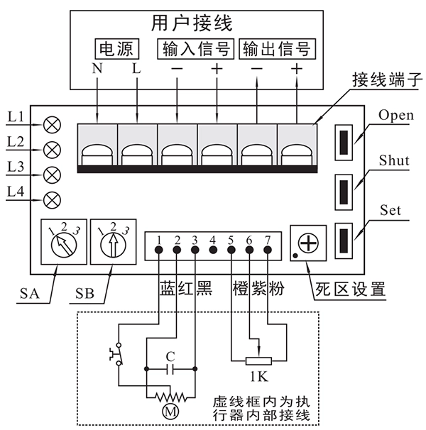
Wiring terminals should be correctly connected as shown in the diagram to avoid damaging the servo controller. Do not connect the “power” terminal to the “input signal” or “output signal” terminals.

4. Servo Controller Panel Explanation
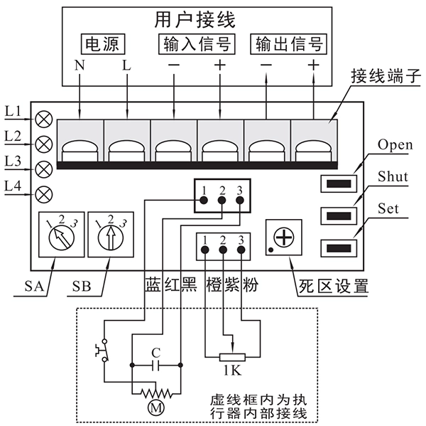
Key Functions:
Open: In “Set State”, press this key to open the valve. Release to stop.
Shut: In “Set State”, press this key to close the valve. Release to stop.
Set: In “Set State”, use with Open or Shut to achieve specific functions.
Selection Switches:
SA (Signal Selection): Switch to select the input signal type (Direct or Reverse) and set state. Ensure to set it in powered-on state for it to take effect.
1 – Direct Action
2 – Set State
3 – Reverse Action
SB (Signal Failure Handling): Select how to handle signal failure.
1 – Valve fully open
2 – Valve maintains position
3 – Valve fully closed
Deadband Setting Potentiometer:
Adjust the deadband value from 0.5% to 5.0% (factory default set at 1.5%). Each adjustment increments the deadband by 0.5%.
Indicators:
L1 (Green): Power on indicator (lights when the controller is powered).
L2 (Red): Input signal failure indicator (lights when the input signal fails).
L3 (Red): Position detection circuit fault indicator (lights when there’s an issue with the position potentiometer wiring or component).
L4 (Red): Mechanical jam fault indicator (lights when there’s a jam in the mechanism).
5. Settings
Entering Set State:
Set the SA switch to position 2, entering the Set State, where functions like stroke calibration, signal failure handling, deadband setting, manual operation, and output current calibration can be configured.
Stroke Calibration:
Fully Closed Calibration:
Use Open or Shut to move the valve to the fully closed position. Press and hold the Set button, then press Shut. Keep both buttons pressed for about 4 seconds until L2 lights up. Release both buttons, completing the full closed calibration.
Fully Open Calibration:
Use Open or Shut to move the valve to the fully open position. Press and hold the Set button, then press Open. Keep both buttons pressed for about 4 seconds until L2 lights up. Release both buttons, completing the full open calibration.
Input Signal Failure Handling:
Use the SB switch to select how the system should handle input signal failure:
1 – Valve fully open
2 – Valve holds position
3 – Valve fully closed
Note: Changing the SB switch is effective even during automatic operation (when SA is set to 1 or 3).
Deadband Value Setting:
Rotate the deadband potentiometer clockwise to increase the deadband, and counterclockwise to decrease it. Each increment changes the deadband by 0.5%. The factory default is 1.5%.
You can manually open or close the valve using the Open or Shut keys in the Set State.
6. Operation
Entering Automatic Operation:
Set the SA switch to 1 or 3 to enter Automatic Operation. In this mode, the actuator’s position and output signal follow the changes in the input signal.
Note:
In Reverse Action, a 4mA input corresponds to a 100% valve opening, while a 20mA input corresponds to a 0% opening.
The servo controller has an accuracy level of Class 1, with a basic error of no more than ±1% and hysteresis less than 1%.
Output Current vs. Valve Position:
| Input Signal | 4mA | 8mA | 12mA | 16mA | 20mA |
|---|---|---|---|---|---|
| Valve Position | 0% | 25% | 50% | 75% | 100% |
| Output Current | 4mA | 8mA | 12mA | 16mA | 20mA |
7. Output Current Calibration
Factory Calibration:
The servo controller is factory-calibrated, so no user adjustments are typically required. However, if the output current at fully closed (4mA) or fully open (20mA) positions deviates by more than 1%, you may need to calibrate it.
Calibration Steps:
Connect a 20mA DC ammeter to the output.
Set the SA switch to 2 to enter Set State.
Press and hold the Set button, then simultaneously press the Open and Shut buttons.
When L2 lights up, release all buttons, and the system will enter 4mA calibration. Adjust the current to 4mA using the Open and Shut keys.
After completing the 4mA calibration, press and hold Set again and wait for L2 to light up. Then release it to enter 20mA calibration and adjust the current to 20mA.
8. Fault Diagnosis and Troubleshooting
Fault Indicator Lights:
L2 Lights Up:
Input signal failure—check the input signal voltage.If the voltage is abnormal (outside the 0.88-4.4V range), check for open circuits, short circuits, or incorrect signal sources.
L3 Lights Up:
Position detection fault—check the potentiometer for issues such as open circuits, short circuits, or damage.L4 Lights Up:
Mechanical jam—check the motor connections and actuator for jams.
Valve and Signal Mismatch:
If the actuator’s stroke does not match the input signal, or if the actuator cannot complete its full stroke, it may indicate a problem with the servo controller or the deadband setting potentiometer circuit.
For further assistance, follow the troubleshooting steps outlined for each fault code.


 鄂公网安备 42018502006527号