


Сверхмалый привод
DCL-02
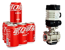
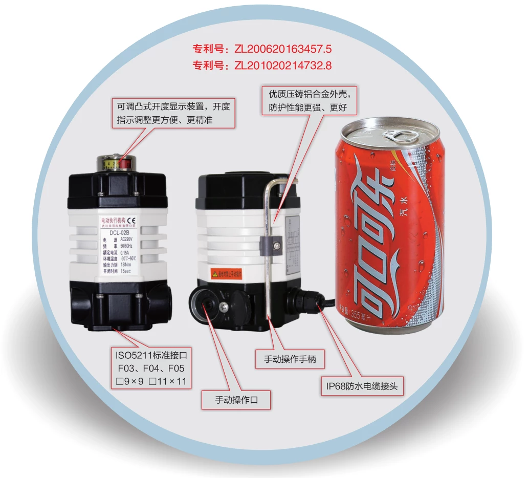
- Small size same as a cola can
- High-strength aluminum alloy shell for strong protection.
- High EMI performance.
Направление движения
Частичный поворот
Демпфер
0 - 270°
Крутящий момент/время работы
9~18Nm
7~60S
Тип обязанности
Модулирование
Вкл. - Выкл.
Напряжение питания
DC24V
AC110V
AC220V
Input/Output Signal
4 - 20 мА
0 - 10V
Интерфейс ввода-вывода
Дополнительные опции
Осушение
Тип обязанности
Модулирование
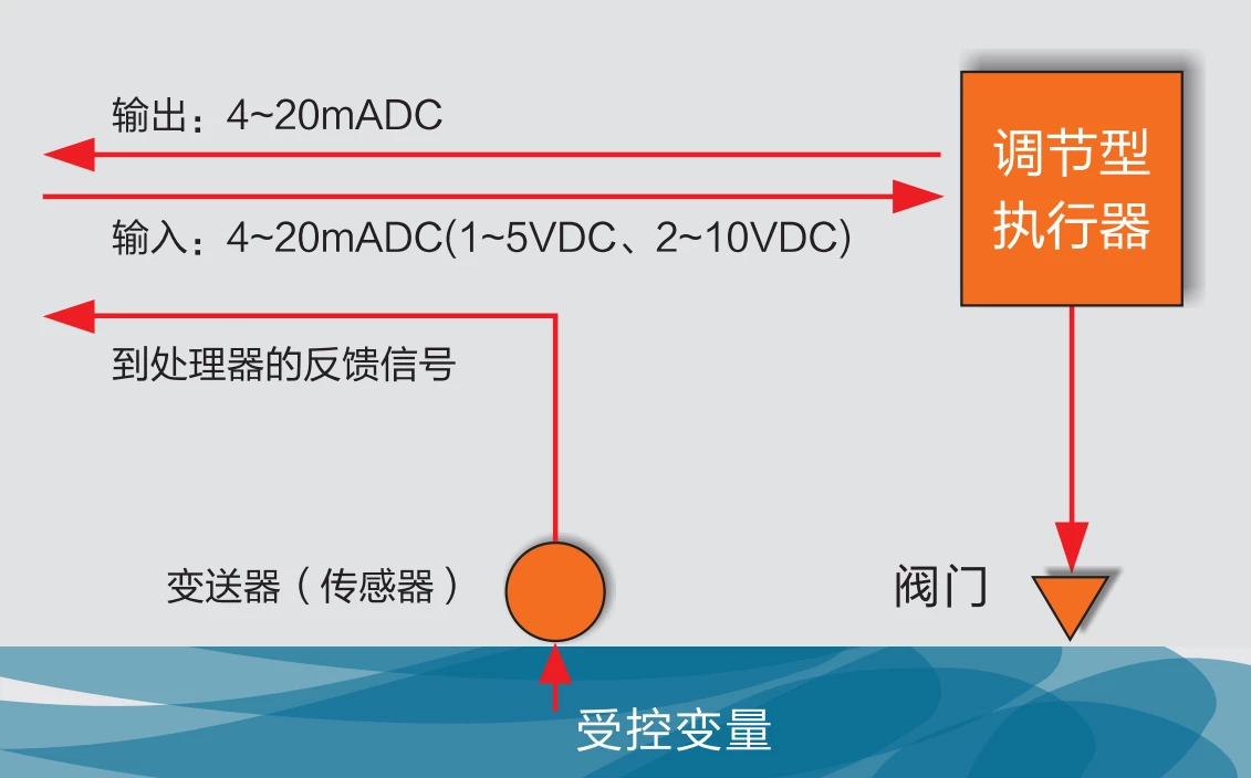
Привод считывает значение заданного положения из системы управления через 4-20 мА, 2-10 В или полевую шину, такую как modbus, ethernet и др.
Затем с помощью алгоритма внутреннего управления приводят клапан в заданное положение.
Привод всегда выдает положение клапана в реальном времени через 4-20 мА, 2-10 В или полевая шина.
Работая в режиме S4, привод может запускаться 1200 раз в час.
Вкл. - Выкл.
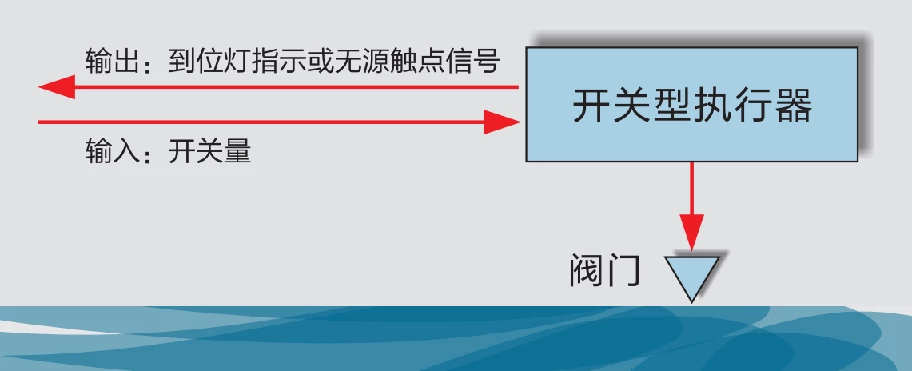
Привод считывает сигнал открытия или закрытия из системы управления через интерфейс IO, например, пассивный сигнал или активный сигнал 24VDC/220VAC.
Затем привод приводит клапан в конечное положение ОТКРЫТО или ЗАКРЫТО в соответствии с требованиями входного сигнала.
При достижении конечного положения привод выдает сигнал обратной связи ОТКРЫТО или ЗАКРЫТО.
В режиме работы S2 привод может непрерывно управлять клапаном в течение 15 минут.
Характеристики
Двигатель с защитой от перегрева
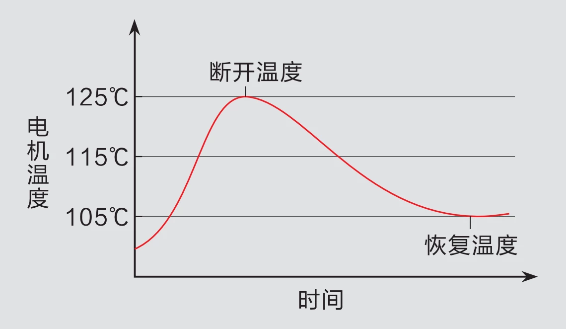
Компания DCL специально разрабатывает двигатель в соответствии с требованиями привода, так что двигатель в приводе DCL может обеспечить высокий пусковой момент при сохранении высокого КПД в фазе запуска, чтобы сделать повышение температуры как можно более низким. В то же время Двигатель имеет малый момент инерции, что обеспечивает высокую точность модуляции.
В двигателе установлено устройство защиты от перегрева, которое отключает питание, когда температура двигателя поднимается выше ограниченной температуры (105℃/85℃ может быть выбрано в зависимости от сценария применения), и подключает питание снова, когда температура восстанавливается ниже нормальной температуры.
Двухпозиционный ограничитель
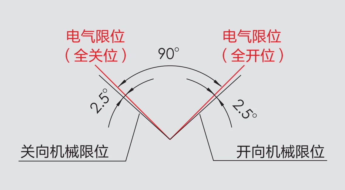
Для защиты клапана от повреждения при превышении угла поворота предусмотрены 2 устройства ограничения положения.
Электрические концевые выключатели устанавливаются в обоих конечных положениях ОТКРЫТЬ и ЗАКРЫТЬ. Таким образом, подача питания на двигатель будет прекращена, чтобы остановить движение клапана после достижения ограниченного конечного положения.
Также на выходном валу установлены 2 механических ограничителя для защиты клапана от выхода за пределы диапазона хода. Механический ограничитель не будет действовать в нормальном режиме работы, поскольку электрический концевой выключатель находится впереди механического ограничителя и сработает до того, как выходной вал достигнет положения, ограниченного механическим ограничителем.
Технические параметры
| Power Supply | DC24V, AC24V, AC110V, AC220V |
| Standard Torque/Time | 18Nm/15S |
| Optional Torque/Time | 9Nm/7S, 18Nm/60S |
| Rotation Angle Range | 0~90° |
| Motor Power/Current | DC24V:8W / 0.7A AC24V:6W / 1.3A AC110V: 6W / 0.3A AC220V:6W / 0.15A |
| Control Circuit | DC24V: E-type/G-type |
| Weight | 1.2kg |
| Insulation Resistance | DC24V/AC24V:100MΩ/250VDC AC110V/AC220V:100MΩ/500VDC |
| Withstand Voltage | DC24V/AC24V: 500VAC for 1 minute |
| Уровень водонепроницаемости | IP67 |
| Installation orientation | 360 ° installation at any angle |
| Electrical Interface | 7-core cable connection |
| Рабочая температура | -25℃ ~ +55℃ |
| Selection of fuses | DC24V:2A AC24V:3A AC110V/AC220V:1A |
| DCL-02 Adjustable Control Parameters | |
| Input Signal | 4~20mA, 0~10V arbitrary calibration |
| выходной сигнал | 4~20mA, 0~10V arbitrary calibration |
| Bus | 485/Modbus/CAN |
| Internet of Things | WIFI/LoRA/4G |
| Basic Error | ≤±1% |
| Check back | ≤1% |
| Hysteresis | Adaptive Hysteresis, customized |
| Reposition Times | 0 times |
| Repeatability Error | ≤1% |
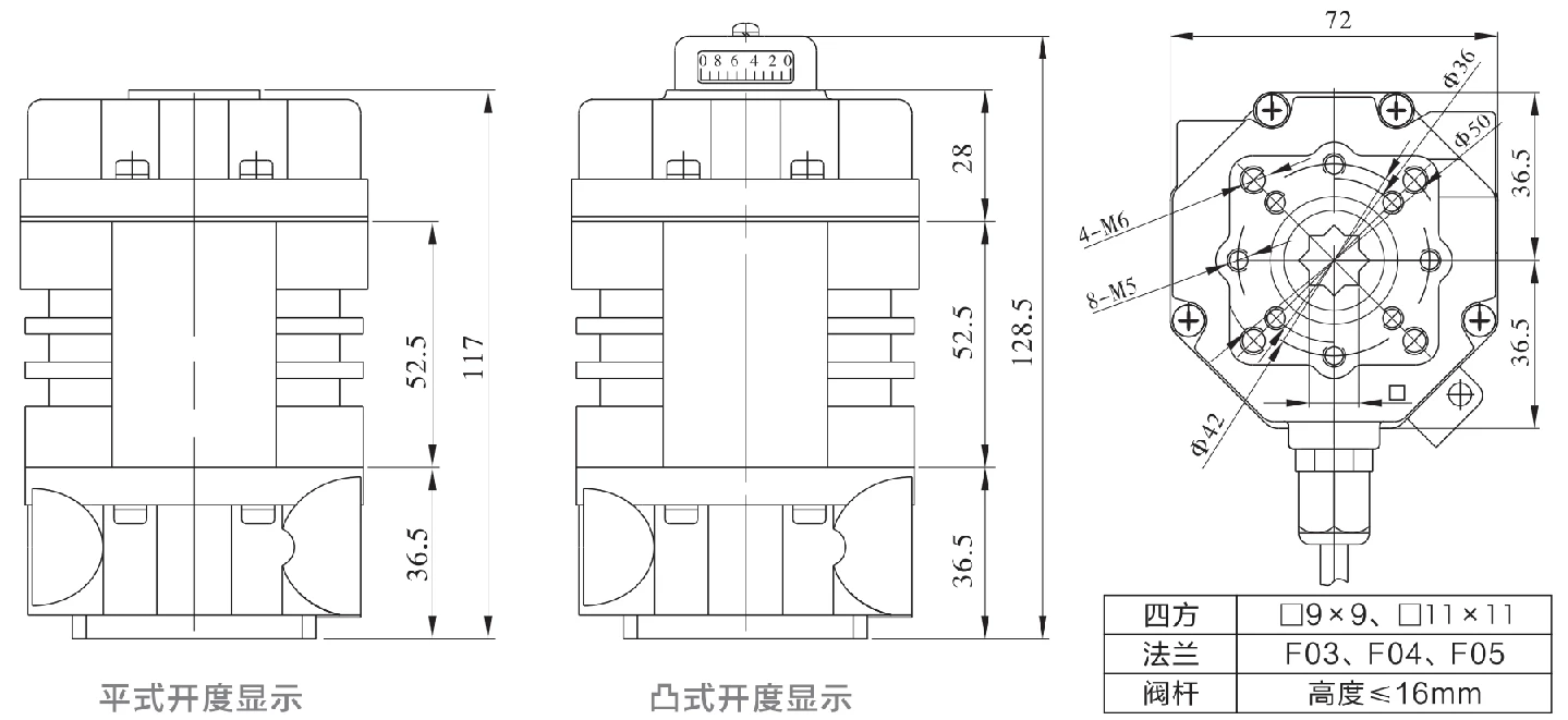
Размеры
Application Circuit
Модулирование
E - Modulating with a control unit
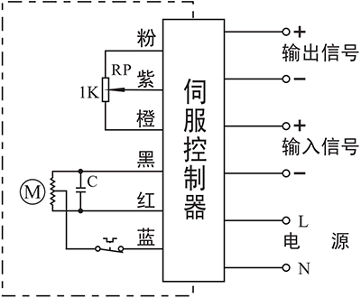
- Input: 4~20mA / 0~10V
- Output: 4~20mA / 0~10V
Connecting Details:
- Connecting AC85-220V supply power line to L and neutral to N.
- Connecting 4-20mA/2-10V input signal source from control system to input-/+.
- Connecting Output -/+ to the system to send out the real-time valve position.
Вкл. - Выкл.
A - With 2 active end-position signal outputs
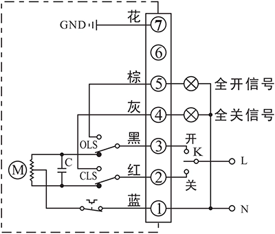
- Control actuator to open or close with K
- The output terminal of end-position OPEN/CLOSE will send out the event as a 220VAC active signal form when the end-position was reached.
Connecting Details:
- Connecting AC85-220V supply power neutral to P1.
- Switch AC85-220V line to CLOSE(P2) to close the valve
- Switch AC85-220V line to OPEN(P3) to open the valve.
- P5 is end-position OPEN terminal which will output a AC220V source which can be used to drive an Indication light when actuator reached end-position of open.
- P6 is end-position OPEN terminal which will output a AC220V source which can be used to drive an Indication light when actuator reached end-position of close.
- Connect earth to P7.
B - With 2 passive end-position switche
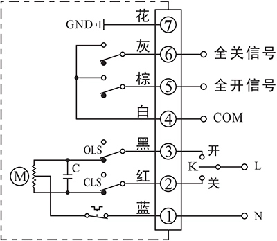
- Control actuator to open or close with K
- The output terminal of end-position OPEN/CLOSE will send out the event as a passive signal form when the end-position was reached.
Connecting Details:
- Connecting AC85-220V supply power neutral to P1.
- Switch AC85-220V line to CLOSE(P2) to close the valve
- Switch AC85-220V line to OPEN(P3) to open the valve.
- P4 is the COM for passive contact signal of end-position OPEN/CLOSE which is normally connected to signal GND.
- P5 is end-position OPEN terminal which will be connected to COM when actuator reached end-position of open.
- P6 is end-position CLOSE terminal which will be connected to COM when actuator reached end-position of close.
- Connect earth to P7.
G - DC motor with 2 end-position switches
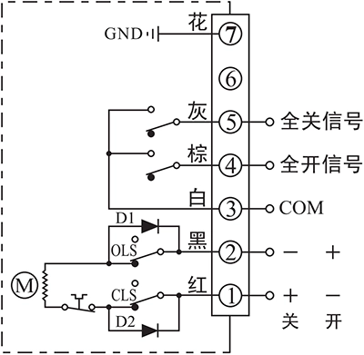
- Control actuator to open or close by the supply power direction between the terminal 1 and 2
- The output terminal of end-position OPEN/CLOSE will send out the event as a passive signal form when the end-position was reached.
Connecting Details:
- Connecting DC24V+ to P1 and DC24V- to P2 to close the valve.
- Connecting DC24V+ to P2 and DC24V- to P1 to close the valve.
- P3 is the COM for passive contact signal of end-position OPEN/CLOSE which is normally connected to signal GND.
- P4 is end-position OPEN terminal which will be connected to COM when actuator reached end-position of open.
- P5 is end-position CLOSE terminal which will be connected to COM when actuator reached end-position of close.
- Connect earth to P7.
Note:
- The circuit inside the dashed box is the internal circuit of actuator. While the circuit outside is a demonstration of electrical connection for using actuator.
- If you have other specific requirements about connecting circuit, please feel free to contact our technical support.


 鄂公网安备 42018502006527号