


In the application of electric actuators’ anti-interference performance, the 4-20mA analog signal significantly outperforms the 2-10V analog signal. Why is this the case?
2-10V Signal Analysis
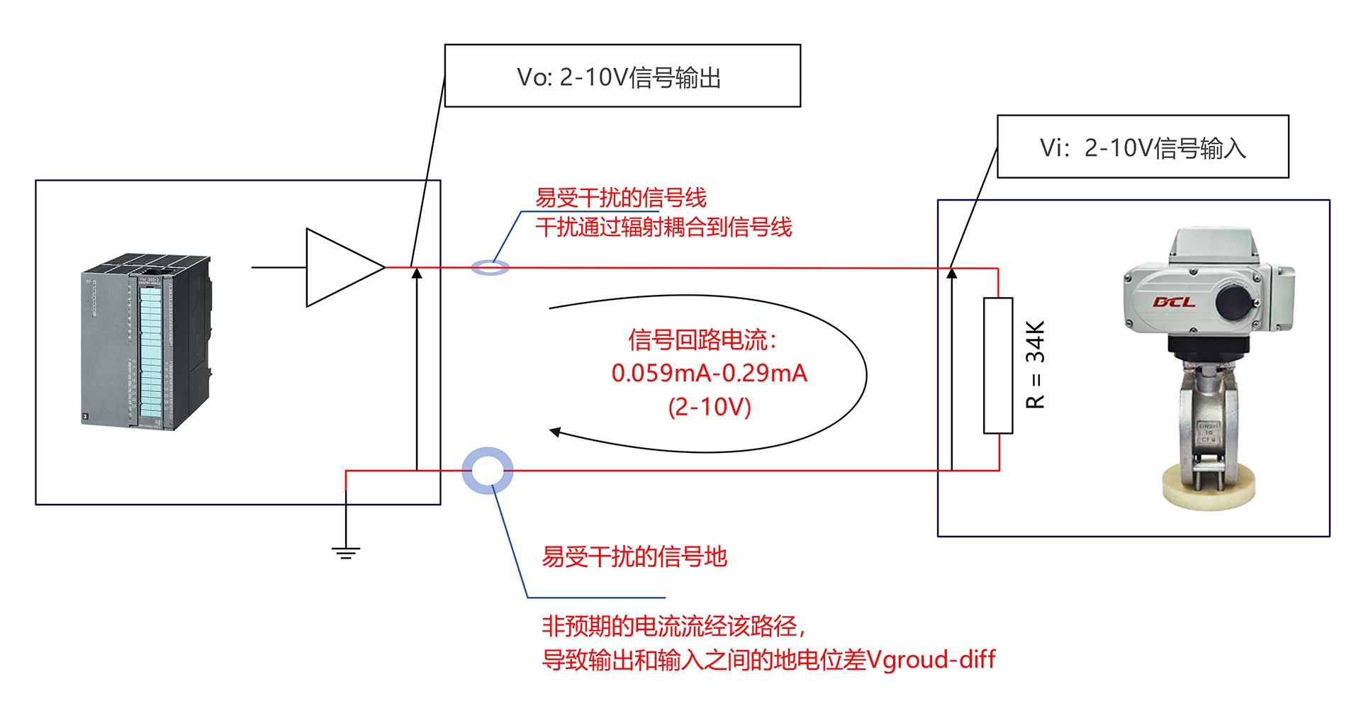
Anti-interference Diagram for 2-10V Signal (DCL Huayi Intelligent Control)
As shown in the diagram above:
When using 2-10V, due to the higher input resistance on the module (R=34K), the input signal current is very low (0.059mA – 0.29mA). The result is that the signal-to-noise ratio along this path is very low, which means the conductive and radiative anti-interference performance is poor. In other words, from an electronic design perspective, this is the most vulnerable part.
In the 2-10V signal path, the output device can only ensure the correctness of the output voltage (Vo) on the controller side (because the voltage feedback point is close to the output pin). On the other hand, the input voltage (Vi) on the actuator side cannot be guaranteed to be correct, because Vi=Vo+Vnoise+Vground−diffVi = Vo + V_{noise} + V_{ground-diff}, where VnoiseV_{noise} og Vground−diffV_{ground-diff} are highly susceptible to interference, causing transient changes that are unavoidable.
The length of the 2-10V signal cable, its internal resistance, and shielding measures significantly affect the anti-interference performance of the 2-10V signal. The longer the cable, the higher the internal resistance, and the poorer the shielding, the worse the 2-10V signal’s resistance to interference. Therefore, 2-10V is commonly used for very short-distance communication.
4-20mA Signal Analysis
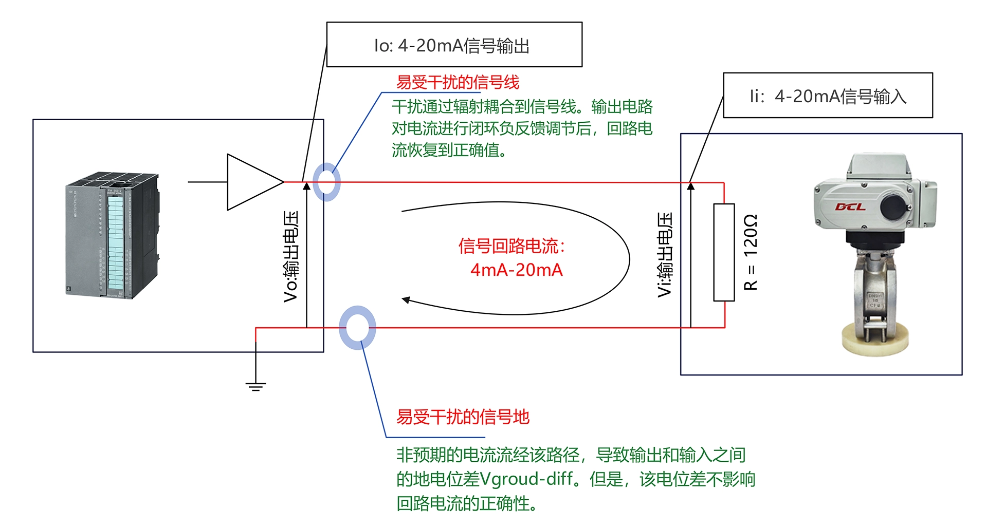
Anti-interference Diagram for 4-20mA Signal (DCL Huayi Intelligent Control)
Compared to 2-10V, 4-20mA addresses two critical weaknesses of the 2-10V signal. As shown in the diagram above:
When using 4-20mA, due to the lower input resistance on the module (R=120 ohms), the input signal current is relatively high (4mA – 20mA). This results in a higher signal-to-noise ratio along this path, meaning the conductive and radiative anti-interference performance is better. As a result, the 4-20mA signal is much harder to interfere with.
In the 4-20mA signal path, the output device can ensure the correctness of the entire output loop current, including both the current on the output side and the current at the actuator input. This is because the feedback sampling target of the output circuit is the current at the 4-20mA loop output end, and the current is equal throughout the entire signal loop. Therefore, the current sampled at the actuator end must be the same as the output current from the controller. Even in the presence of interference and ground potential inconsistencies, the 4-20mA output circuit can ensure the correctness of the signal current through active negative feedback adjustment.
The length of the 4-20mA signal cable and its internal resistance have little impact on the anti-interference performance of the 4-20mA signal. Therefore, 4-20mA is commonly used for long-distance communication.
Conclusion
In conclusion, the 4-20mA signal has significantly better anti-interference performance than the 2-10V signal in industrial environments. This also holds true for applications involving electric actuators.


 鄂公网安备 42018502006527号