


This guide applies to the switch-type actuators of the DCL explosion-proof series, standard series, and quick-open series. The models are as follows:
Weather-proof Actuator: DCL-05, DCL-10, DCL-20, DCL-40, DCL-60, DCL-100, DCL-160, DCL-250
Explosion-Proof Actuator: DCL-Ex05, DCL-Ex10, DCL-Ex20, DCL-Ex40, DCL-Ex60
Quick-Turn Actuator: DCL-K05, DCL-K10, DCL-K20, DCL-K40, DCL-K100
Common Faults and Troubleshooting Methods
| 결함 | Possible Causes | 문제 해결 방법 |
|---|---|---|
| Actuator does not open or close at startup | 1. Incorrect wiring. 2. Incorrect power supply. 3. Faulty control switch or relay. 4. Control system mismatch. 5. Multiple actuators or actuator in parallel with other devices. | 1. Check the wiring against the actuator’s wiring diagram to ensure it is correct. 2. Verify power supply output voltage is ±10% of rated voltage, and the current is at least three times the actuator’s rated current. 3. Use a multimeter to measure input voltage at the actuator’s control terminal and confirm it matches expected values. 4. Use a mechanical switch to test actuator operation. If it works, verify the control system output logic. 5. Switch-type actuators should not be connected in parallel with other devices; use a single control circuit. |
| Actuator only opens or closes, not both | 1. Incorrect wiring. 2. Incorrect full open/full close cam settings. | 1. Use a mechanical switch to test actuator functionality. If it works, verify the control system output logic. 2. Check actuator’s wiring against the wiring diagram. 3. Adjust the cam settings according to the “How to Set Switch-type Electric Valves” manual. |
| Actuator stops in the middle of its stroke | 1. Valve is stuck. 2. Solid particles in the fluid medium causing valve blockage. 3. Incorrect full open/full close block settings. | 1. Check if the valve is stuck. Remove obstructions and retry after the actuator cools down from overload protection. 2. Inspect the fluid medium for solid particles. Remove any blockage and retry after cooling. 3. Adjust block settings according to the “How to Set Switch-type Electric Valves” manual. |
| Cannot turn the actuator with the handwheel | 1. Solid particles in the fluid medium causing valve blockage. 2. Valve is stuck. 3. Actuator’s reduction mechanism is damaged. | 1. Check fluid medium for particles causing blockage. Remove obstructions and retry after cooling. 2. Inspect valve for any stuck parts. Remove blockage and retry. 3. If actuator cannot be turned by hand, remove it from the valve. If it still doesn’t turn, replace with a new actuator. |
| No output from position feedback signal | 1. Incorrect switch wiring. 2. Incorrect full open/full close cam settings. 3. Overcurrent causing damage to the position feedback signal switch. | 1. Check wiring of the switch against the actuator’s wiring diagram to ensure it is correct. 2. Verify full open/full close cam is properly compressing the position feedback switch. 3. Measure the position feedback circuit to check if the switch is intact and properly connected. |
Please check if the operating conditions meet the parameter requirements.
Electric actuators may fail due to improper use or operating in incorrect conditions. To ensure long-term, trouble-free operation, the actuator must be used within the operating conditions specified in the product datasheet.
Power Supply Voltage: The supply voltage must be within the actuator’s rated operating voltage range. Overvoltage or undervoltage may reduce the actuator’s lifespan.
Power Supply Current: Since the motor’s starting current is significantly higher than the rated current, please ensure that the power supply can provide a current capacity at least 3 times the actuator’s rated current to ensure reliable operation.
Temperature: Ensure that the actuator operates within the rated temperature range. Operating the actuator outside the specified temperature range may cause malfunction, reduced lifespan, or eventual failure.
Environment: The DCL switch-type actuators are rated at IP67 for wind and rain protection. They are generally suitable for both indoor and outdoor use, providing protection against rain, splashes, and UV exposure (sunlight), which typically extends the product’s lifespan. Extremely corrosive environments may cause premature failure of electronic components. Do not use non-explosion-proof actuators in explosive atmospheres.
Duty Cycle: The duty cycle of the DCL switch-type actuator is 70% (42 seconds of operation per minute, with a required 18 seconds off). Exceeding a 70% duty cycle will trigger thermal protection for the motor.
Check if the wiring of the actuator is correct.
Ensure that all electrical connections are properly made according to the wiring diagram provided in the product manual. Incorrect wiring can lead to malfunction or damage to the actuator. Verify the following:
The power supply connections are properly secured and there are no loose wires.
The control signal wiring is correctly connected, ensuring polarity and signal type are properly matched.
The ground connection (if applicable) is properly established to avoid electrical hazards.
Double-check the connection of any external components, such as limit switches or feedback devices, to ensure they are wired correctly.
켜기 - 끄기
A - 2개의 활성 엔드 포지션 신호 출력 포함
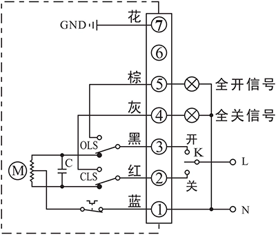
- K로 액추에이터를 제어하여 열거나 닫습니다.
- 종단 위치 OPEN/CLOSE의 출력 단자는 종단 위치에 도달하면 220VAC 활성 신호 형태로 이벤트를 전송합니다.
세부 정보 연결:
- AC85-220V 공급 전원 중립을 P1에 연결합니다.
- AC85-220V 라인을 CLOSE(P2)로 전환하여 밸브를 닫습니다.
- AC85-220V 라인을 OPEN(P3)으로 전환하여 밸브를 엽니다.
- P5는 액추에이터가 열림의 끝 위치에 도달했을 때 표시등을 구동하는 데 사용할 수 있는 AC220V 소스를 출력하는 끝 위치 OPEN 단자입니다.
- P6은 액추에이터가 닫힘의 끝 위치에 도달했을 때 표시등을 구동하는 데 사용할 수 있는 AC220V 소스를 출력하는 끝 위치 OPEN 단자입니다.
- 접지를 P7에 연결합니다.
B - 패시브 엔드 포지션 스위치 2개 포함
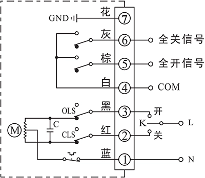
- K로 액추에이터를 제어하여 열거나 닫습니다.
- 엔드 포지션 OPEN/CLOSE의 출력 단자는 엔드 포지션에 도달하면 수동 신호 형태로 이벤트를 전송합니다.
세부 정보 연결:
- AC85-220V 공급 전원 중립을 P1에 연결합니다.
- AC85-220V 라인을 CLOSE(P2)로 전환하여 밸브를 닫습니다.
- AC85-220V 라인을 OPEN(P3)으로 전환하여 밸브를 엽니다.
- P4는 일반적으로 신호 GND에 연결되는 종단 위치 OPEN/CLOSE의 패시브 접점 신호용 COM입니다.
- P5는 액추에이터가 열림의 끝 위치에 도달하면 COM에 연결되는 끝 위치 열림 단자입니다.
- P6은 액추에이터가 닫힘의 끝 위치에 도달하면 COM에 연결되는 끝 위치 닫힘 단자입니다.
- 접지를 P7에 연결합니다.
G - 종단 위치 스위치가 2개인 DC 모터
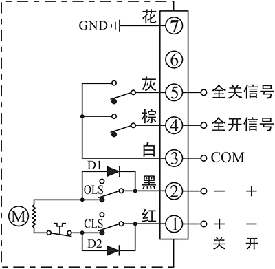
- 단자 1과 2 사이의 공급 전원 방향에 따라 액추에이터를 열거나 닫도록 제어합니다.
- 엔드 포지션 OPEN/CLOSE의 출력 단자는 엔드 포지션에 도달하면 수동 신호 형태로 이벤트를 전송합니다.
세부 정보 연결:
- DC24V+를 P1에, DC24V-를 P2에 연결하여 밸브를 닫습니다.
- DC24V+를 P2에, DC24V-를 P1에 연결하여 밸브를 닫습니다.
- P3은 일반적으로 신호 GND에 연결되는 종단 위치 OPEN/CLOSE의 패시브 접점 신호용 COM입니다.
- P4는 액추에이터가 열림의 끝 위치에 도달하면 COM에 연결되는 끝 위치 열림 단자입니다.
- P5는 액추에이터가 닫힘의 끝 위치에 도달하면 COM에 연결되는 끝 위치 CLOSE 단자입니다.
- 접지를 P7에 연결합니다.
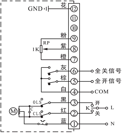
H - 종단 위치 스위치 2개가 있는 3상 380VAC 모터
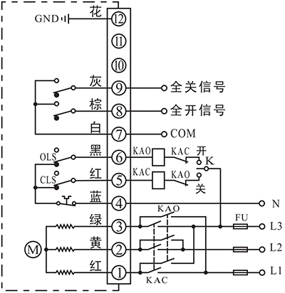
- 외부 인버터로 액추에이터를 열거나 닫아 공급 전력의 위상을 변경할 수 있습니다.
- 엔드 포지션 OPEN/CLOSE의 출력 단자는 엔드 포지션에 도달하면 수동 신호 형태로 이벤트를 전송합니다.
세부 정보 연결:
- 3상 AC380V 인버터 출력을 P1, P2, P3에 연결하면 3상 순서를 변경하여 밸브를 열거나 닫도록 액추에이터를 제어할 수 있습니다.
- AC380V 중성선을 N(P4)에 연결합니다.
- P5는 인버터 3상 순서를 제어하기 위해 외부 스위치와 협력하는 데 사용됩니다. 이 단자는 액추에이터가 닫힘의 최종 위치에 있지 않을 때 N(P4)에 연결되고 액추에이터가 닫힘의 최종 위치에 도달하면 N(P4)에서 연결이 해제됩니다.
- P6은 인버터 3상 순서를 제어하기 위해 외부 스위치와 협력하는 데 사용됩니다. 이 단자는 액추에이터가 OPEN의 최종 위치에 있지 않을 때 N(P4)에 연결되고 액추에이터가 OPEN의 최종 위치에 도달한 후에는 N(P4)에서 분리됩니다.
- P7은 일반적으로 신호 GND에 연결되는 종단 위치 OPEN/CLOSE의 패시브 접점 신호용 COM입니다.
- P8은 액추에이터가 열림의 끝 위치에 도달하면 COM에 연결되는 끝 위치 열림 단자입니다.
- P9는 액추에이터가 닫힘의 끝 위치에 도달하면 COM에 연결되는 끝 위치 닫힘 단자입니다.
- 접지를 P12에 연결합니다.
인치 및 위치 지정
F - 포지셔닝 유닛 포함
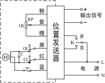
- K로 액추에이터를 제어하여 열거나 닫습니다.
- 실시간 밸브 위치는 4-20mA 신호로 전송됩니다.
세부 정보 연결:
- AC85-220V 공급 전원선을 L에 연결하고 중성선을 N에 연결합니다.
- AC85-220V 라인을 CLOSE(P2)로 전환하여 밸브를 닫습니다.
- AC85-220V 라인을 OPEN(P3)으로 전환하여 밸브를 엽니다.
- 출력 -/+를 시스템에 연결하여 실시간 밸브 위치를 전송합니다.
C - 1KΩ/500Ω 전위차계 사용
- K로 액추에이터를 제어하여 열거나 닫습니다.
- 실시간 밸브 위치는 전위차계 저항 값으로 전송됩니다.
세부 정보 연결:
- AC85-220V 공급 전원 중립을 P1에 연결합니다.
- AC85-220V 라인을 CLOSE(P2)로 전환하여 밸브를 닫습니다.
- AC85-220V 라인을 OPEN(P3)으로 전환하여 밸브를 엽니다.
- P4는 전위차계의 로우측으로, 일반적으로 신호 GND에 연결됩니다.
- 제어 시스템의 신호 입력을 P5에 연결합니다. 액추에이터가 밸브를 열면 P4와 P5 사이의 저항 값은 높아지는 반면, P5와 P6 사이의 값은 낮아집니다.
- P6은 일반적으로 신호 전원에 연결되는 포텐셔미터의 높은 쪽입니다.
- 접지를 P7에 연결합니다.
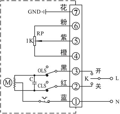
D - 전위차계 및 엔드 포지션 피드백 포함
- K로 액추에이터를 제어하여 열거나 닫습니다.
- 실시간 밸브 위치는 전위차계 저항 값으로 전송됩니다.
- 엔드 포지션 OPEN/CLOSE의 출력 단자는 엔드 포지션에 도달하면 수동 신호 형태로 이벤트를 전송합니다.
세부 정보 연결:
- AC85-220V 공급 전원 중립을 P1에 연결합니다.
- AC85-220V 라인을 CLOSE(P2)로 전환하여 밸브를 닫습니다.
- AC85-220V 라인을 OPEN(P3)으로 전환하여 밸브를 엽니다.
- P4는 일반적으로 신호 GND에 연결되는 종단 위치 OPEN/CLOSE의 패시브 접점 신호용 COM입니다.
- P5는 액추에이터가 열림의 끝 위치에 도달하면 COM에 연결되는 끝 위치 열림 단자입니다.
- P6은 액추에이터가 닫힘의 끝 위치에 도달하면 COM에 연결되는 끝 위치 닫힘 단자입니다.
- P7은 전위차계의 로우측으로, 일반적으로 신호 GND에 연결됩니다.
- 제어 시스템의 신호 입력을 P8에 연결합니다. 액추에이터가 밸브를 열면 P7과 P8 사이의 저항 값은 높아지는 반면, P8과 P9 사이의 값은 낮아집니다.
- P9는 일반적으로 신호 전원에 연결되는 포텐셔미터의 높은 쪽입니다.
- 접지를 P12에 연결합니다.
참고: 참고
- 점선 상자 안의 회로는 액추에이터의 내부 회로입니다. 외부 회로는 액추에이터 사용을 위한 전기 연결 데모입니다.
- 회로 연결에 대한 기타 구체적인 요구 사항이 있는 경우 언제든지 기술 지원팀에 문의하시기 바랍니다.


 鄂公网安备 42018502006527号