Technical Parameters
| Power Supply | DC24V, AC24V, AC110V, AC220V, AC380V |
| Time/torque | DC24V: 2S/15Nm, 5S/30Nm AC24V/AC110V/AC220V/AC380V: 3S/15Nm, 6S/30Nm |
| control circuit | G-type/A-type/B-type/H-type |
| Rotation Angle | Adjustable from 0 to 270 ° |
| Motor Power/Current | DC24V: 13W/3.0A AC24V: 10W/1.50A AC110V: 10W/0.24A AC220V: 10W/0.16A AC380V: 10W/0.07A |
| Weight | 2.5Kg |
| Insulation Resistance | DC24V: 100MΩ/250VDC AC24V~380V: 100MΩ/500VDC |
| Withstand Voltage | DC/AC24V: 500VAC for 1 minute |
| Water Proof Level | IP67 |
| Installation | 360 ° installation at any angle |
| Electrical Interface | G1/2 waterproof cable joint |
| Working Temperature | -25℃ ~ +55℃ |
| Optional Function | Dehumidification heater, convex indicator |
| Modulation Parameters | |
| Input Signal | 4~20mA, 0~10V arbitrary calibration |
| output Signal | 4~20mA, 0~10V arbitrary calibration |
| Bus | 485/Modbus/CAN |
| Internet of Things | WIFI/LoRA/4G |
| Basic Error | ≤±1% |
| Return Error | ≤1% |
| Hysteresis | Adjustable from 0.5% to 5.0% |
| Reposition Times | 0 times |
| Repeatability Error | ≤1% |
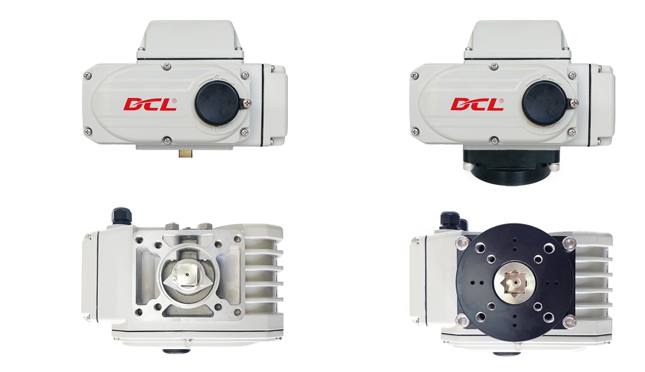
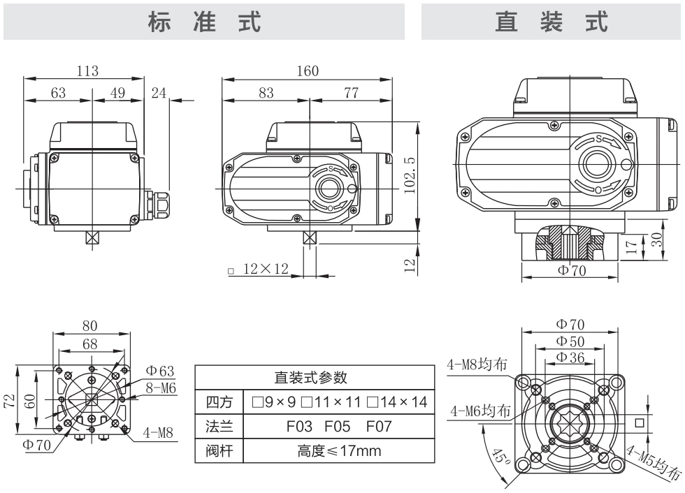
Dimensions
Application Circuit
Modulating
E - Modulating with a control unit
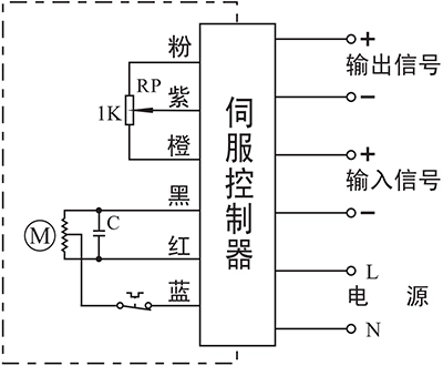
- Input: 4~20mA / 0~10V
- Output: 4~20mA / 0~10V
- Field Bus:Modbus / CAN
- IIot:WIFI/LoRA/4G DTU
Connecting Details:
- Connecting AC85-220V supply power line to L and neutral to N.
- Connecting 4-20mA/2-10V input signal source from control system to input-/+.
- Connecting Output -/+ to the system to send out the real-time valve position.
Inching and positioning
F - With a positioning unit
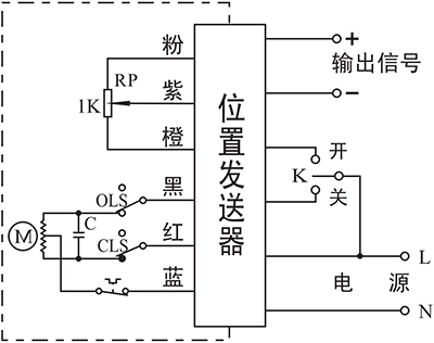
- Control actuator to open or close with K
- The real-time valve position will be send out as a 4-20mA signal.
Connecting Details:
- Connecting AC85-220V supply power line to L and neutral to N.
- Switch AC85-220V line to CLOSE(P2) to close the valve.
- Switch AC85-220V line to OPEN(P3) to open the valve.
- Connecting Output -/+ to the system to send out the real-time valve position.
C - With a 1KΩ/500Ω potentiometer
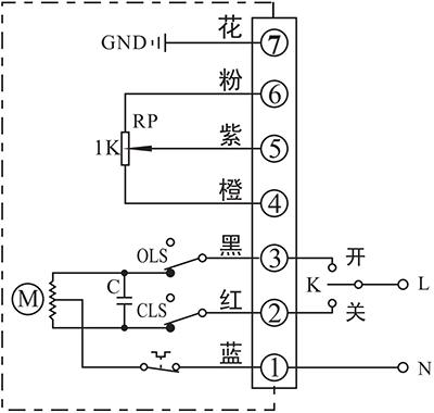
- Control actuator to open or close with K
- The real-time valve position will be send out as a potentiometer resistance value
Connecting Details:
- Connecting AC85-220V supply power neutral to P1.
- Switch AC85-220V line to CLOSE(P2) to close the valve
- Switch AC85-220V line to OPEN(P3) to open the valve.
- P4 is the low side of potentiometer that is normally connected to signal GND.
- Connecting signal input of control system to P5. The resistance value between P4 and P5 will become higher as actuator opening the valve, while the value between P5 and P6 will become lower.
- P6 is the high side of potentiometer that is normally connected to signal power.
- Connect earth to P7.
D - With a potentiometer and end-position feedback
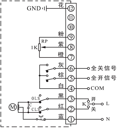
- Control actuator to open or close with K
- The real-time valve position will be send out as a potentiometer resistance value
- The output terminal of end-position OPEN/CLOSE will send out the event as a passive signal form when the end-position was reached.
Connecting Details:
- Connecting AC85-220V supply power neutral to P1.
- Switch AC85-220V line to CLOSE(P2) to close the valve
- Switch AC85-220V line to OPEN(P3) to open the valve.
- P4 is the COM for passive contact signal of end-position OPEN/CLOSE which is normally connected to signal GND.
- P5 is end-position OPEN terminal which will be connected to COM when actuator reached end-position of open.
- P6 is end-position CLOSE terminal which will be connected to COM when actuator reached end-position of close.
- P7 is the low side of potentiometer that is normally connected to signal GND.
- Connecting signal input of control system to P8. The resistance value between P7 and P8 will become higher as actuator opening the valve, while the value between P8 and P9 will become lower.
- P9 is the high side of potentiometer that is normally connected to signal power.
- Connect earth to P12.
ON - OFF
A - With 2 active end-position signal outputs
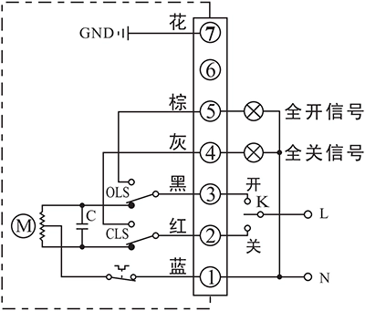
- Control actuator to open or close with K
- The output terminal of end-position OPEN/CLOSE will send out the event as a 220VAC active signal form when the end-position was reached.
Connecting Details:
- Connecting AC85-220V supply power neutral to P1.
- Switch AC85-220V line to CLOSE(P2) to close the valve
- Switch AC85-220V line to OPEN(P3) to open the valve.
- P5 is end-position OPEN terminal which will output a AC220V source which can be used to drive an Indication light when actuator reached end-position of open.
- P6 is end-position OPEN terminal which will output a AC220V source which can be used to drive an Indication light when actuator reached end-position of close.
- Connect earth to P7.
B - With 2 passive end-position switches
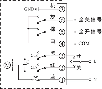
- Control actuator to open or close with K
- The output terminal of end-position OPEN/CLOSE will send out the event as a passive signal form when the end-position was reached.
Connecting Details:
- Connecting AC85-220V supply power neutral to P1.
- Switch AC85-220V line to CLOSE(P2) to close the valve
- Switch AC85-220V line to OPEN(P3) to open the valve.
- P4 is the COM for passive contact signal of end-position OPEN/CLOSE which is normally connected to signal GND.
- P5 is end-position OPEN terminal which will be connected to COM when actuator reached end-position of open.
- P6 is end-position CLOSE terminal which will be connected to COM when actuator reached end-position of close.
- Connect earth to P7.
G - DC motor with 2 end-position switches
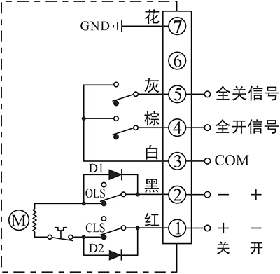
- Control actuator to open or close by the supply power direction between the terminal 1 and 2
- The output terminal of end-position OPEN/CLOSE will send out the event as a passive signal form when the end-position was reached.
Connecting Details:
- Connecting DC24V+ to P1 and DC24V- to P2 to close the valve.
- Connecting DC24V+ to P2 and DC24V- to P1 to close the valve.
- P3 is the COM for passive contact signal of end-position OPEN/CLOSE which is normally connected to signal GND.
- P4 is end-position OPEN terminal which will be connected to COM when actuator reached end-position of open.
- P5 is end-position CLOSE terminal which will be connected to COM when actuator reached end-position of close.
- Connect earth to P7.
H - 3 phase 380VAC motor with 2 end-position switches
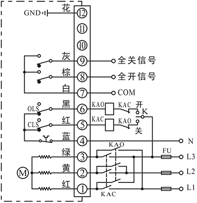
- Control actuator to open or close by an external inverter to change the phase of supply power.
- The output terminal of end-position OPEN/CLOSE will send out the event as a passive signal form when the end-position was reached.
Connecting Details:
- Connecting a 3 phase AC380V inverter output to P1, P2 and P3, then the actuator can be controlled to open or close the valve by change the 3 phase order.
- Connecting AC380V neutral to N(P4).
- P5 is used for cooperating with an external switch to control the inverter 3 phase order. This terminal is connected to N(P4) when actuator is not in end-position of CLOSE and disconnected from N(P4) after actuator reached end-position of CLOSE.
- P6 is used for cooperating with an external switch to control the inverter 3 phase order. This terminal is connected to N(P4) when actuator is not in end-position of OPEN and disconnected from N(P4) after actuator reached end-position of OPEN.
- P7 is the COM for passive contact signal of end-position OPEN/CLOSE which is normally connected to signal GND.
- P8 is end-position OPEN terminal which will be connected to COM when actuator reached end-position of open.
- P9 is end-position CLOSE terminal which will be connected to COM when actuator reached end-position of close.
- Connect earth to P12.
Note:
- The circuit inside the dashed box is the internal circuit of actuator. While the circuit outside is a demonstration of electrical connection for using actuator.
- If you have other specific requirements about connecting circuit, please feel free to contact our technical support.












 鄂公网安备 42018502006527号