
Produits

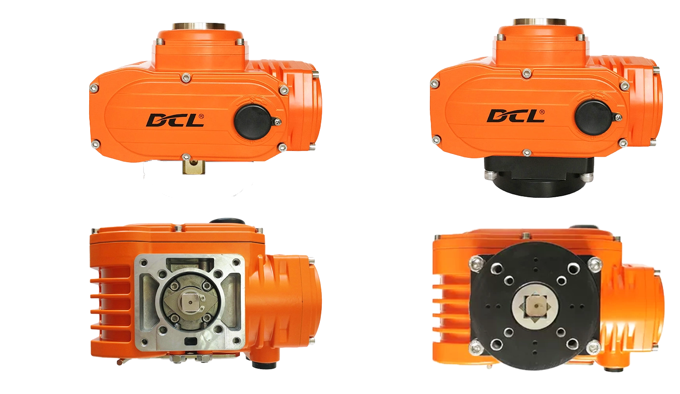
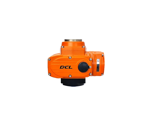
Technical Parameters

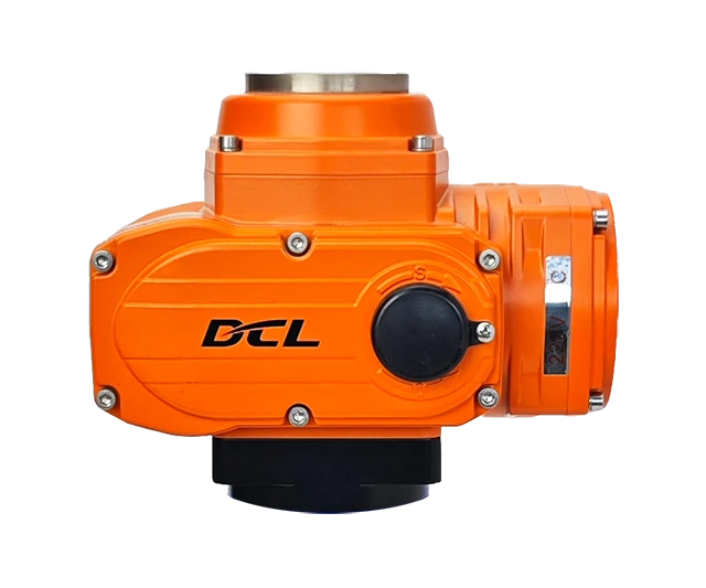
Explosion Proof GradeExd II CT4Gb
Power SupplyDC24V, AC110V, AC220V, AC380V
Standard Torque/TimeDC24V: 200Nm/60S
AC110V/AC220V/AC380V: 200Nm/30S
Optional Torque/Time50Nm/15S, 200Nm/60S
Rotation Angle RangeAdjustable from 0 to 90 degrees
Motor Power/CurrentDC24V: 25W/3.12A
AC110V: 40W/0.63A
AC220V: 40W/0.35A
AC380V: 30W /0.19A
Control CircuitType A/B/C/D/E/F/G/H
Weight5.5kg
Insulation Resistance DC24V: 100MΩ/250VDC
AC110V/AC220V/AC380V: 100MΩ/500VDC
Withstand VoltageDC24V/AC24V: 500VAC for 1 minute
Water Proof LevelIP68
Installation360 ° installation at any angle
Electrical Interface2-M20x1.5 explosion-proof plug, users should install corresponding explosion-proof cable connectors according to the selected cable during use
Working Temperature-20℃~﹢60℃
Optional Function♦ Over torque protection ♦ Dehumidification heater
Modulation Parameters
Signal d'entrée4~20mA, 0~10V arbitrary calibration
output Signal4~20mA, 0~10V arbitrary calibration
Bus485/Modbus/CAN
Internet of ThingsWIFI/LoRA/4G
Basic Error≤±1%
Return Error≤1%
HysteresisAdjustable from 0.5% to 5.0%
Reposition Times0 times
Repeatability Error≤1%

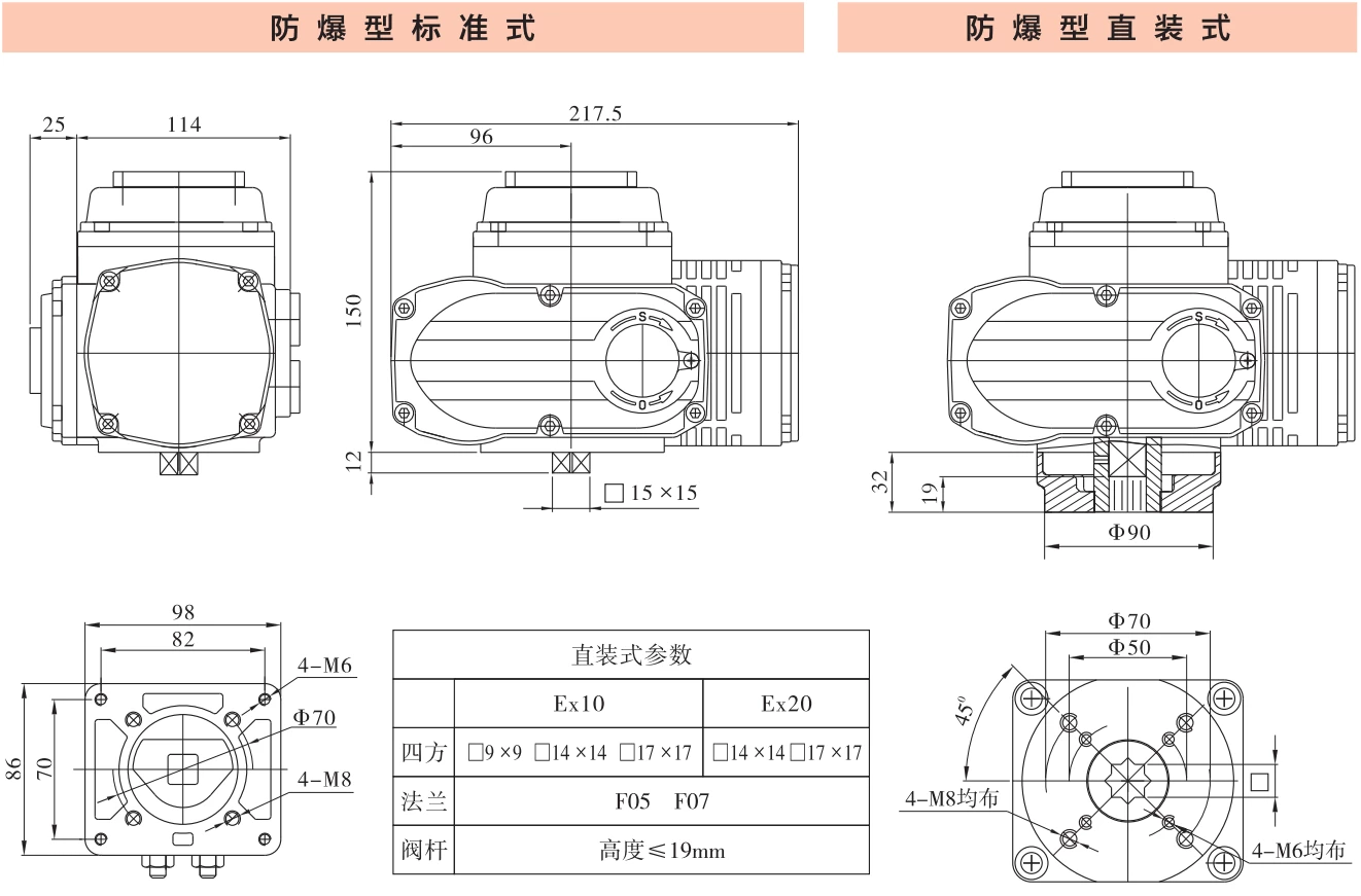
Dimensions

华易防爆执行器安装形式 | DCL Explosion-Proof Actuator Installation Demension
华易Exd II CT4Gb执行器 DCL-Ex10 DCL-Ex20 外型安装尺寸

Application Circuit

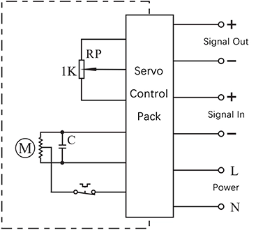
Modulation

E - Modulating with a control unit

  • Input: 4~20mA / 0~10V
  • Output: 4~20mA / 0~10V
  • Field Bus:Modbus / CAN
  • IIot:WIFI/LoRA/4G DTU


Connecting Details:

  1. Connecting AC85-220V supply power line to L and neutral to N.
  2. Connecting 4-20mA/2-10V input signal source from control system to input-/+.
  3. Connecting Output -/+ to the system to send out the real-time valve position.

Inching and positioning

F - With a positioning unit

  • Control actuator to open or close with K
  • The real-time valve position will be send out as a 4-20mA signal.


Connecting Details:

  1. Connecting AC85-220V supply power line to L and neutral to N.
  2. Switch AC85-220V line to CLOSE(P2) to close the valve.
  3. Switch AC85-220V line to OPEN(P3) to open the valve.
  4. Connecting Output -/+ to the system to send out the real-time valve position.

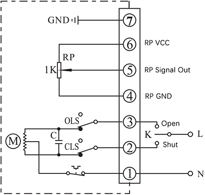
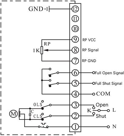
C - With a 1KΩ/500Ω potentiometer

  • Control actuator to open or close with K
  • The real-time valve position will be send out as a potentiometer resistance value


Connecting Details:

  1. Connecting AC85-220V supply power neutral to P1.
  2. Switch AC85-220V line to CLOSE(P2) to close the valve
  3. Switch AC85-220V line to OPEN(P3) to open the valve.
  4. P4 is the low side of potentiometer that is normally connected to signal GND.
  5. Connecting signal input of  control system to P5. The resistance value between P4 and P5 will become higher as actuator opening the valve, while the value between P5 and P6 will become lower.
  6. P6 is the high side of potentiometer that is normally connected to signal power.
  7. Connect earth to P7.

D - With a potentiometer and end-position feedback

  • Control actuator to open or close with K
  • The real-time valve position will be send out as a potentiometer resistance value
  • The output terminal of end-position OPEN/CLOSE will send out the event as a passive signal form when the end-position was reached.


Connecting Details:

  1. Connecting AC85-220V supply power neutral to P1.
  2. Switch AC85-220V line to CLOSE(P2) to close the valve
  3. Switch AC85-220V line to OPEN(P3) to open the valve.
  4. P4 is the COM for passive contact signal of end-position OPEN/CLOSE which is normally connected to signal GND.
  5. P5 is end-position OPEN terminal which will be connected to COM when actuator reached end-position of open.
  6. P6 is end-position CLOSE terminal which will be connected to COM when actuator reached end-position of close.
  7. P7 is the low side of potentiometer that is normally connected to signal GND.
  8. Connecting signal input of  control system to P8. The resistance value between P7 and P8 will become higher as actuator opening the valve, while the value between P8 and P9 will become lower.
  9. P9 is the high side of potentiometer that is normally connected to signal power.
  10. Connect earth to P12.

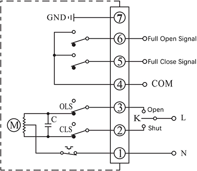
ON - OFF

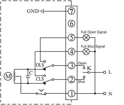
A - With 2 active end-position signal outputs

  • Control actuator to open or close with K
  • The output terminal of end-position OPEN/CLOSE will send out the event as a 220VAC active signal form when the end-position was reached.


Connecting Details:

  1. Connecting AC85-220V supply power neutral to P1.
  2. Switch AC85-220V line to CLOSE(P2) to close the valve
  3. Switch AC85-220V line to OPEN(P3) to open the valve.
  4. P5 is end-position OPEN terminal which will output a AC220V source which can be used to drive an Indication light when actuator reached end-position of open.
  5. P6 is end-position OPEN terminal which will output a AC220V source which can be used to drive an Indication light when actuator reached end-position of close.
  6. Connect earth to P7.

B - With 2 passive end-position switches

  • Control actuator to open or close with K
  • The output terminal of end-position OPEN/CLOSE will send out the event as a passive signal form when the end-position was reached.


Connecting Details:

  1. Connecting AC85-220V supply power neutral to P1.
  2. Switch AC85-220V line to CLOSE(P2) to close the valve
  3. Switch AC85-220V line to OPEN(P3) to open the valve.
  4. P4 is the COM for passive contact signal of end-position OPEN/CLOSE which is normally connected to signal GND.
  5. P5 is end-position OPEN terminal which will be connected to COM when actuator reached end-position of open.
  6. P6 is end-position CLOSE terminal which will be connected to COM when actuator reached end-position of close.
  7. Connect earth to P7.

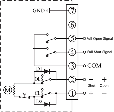
G - DC motor with 2 end-position switches

  • Control actuator to open or close by the supply power direction between the terminal 1 and 2
  • The output terminal of end-position OPEN/CLOSE will send out the event as a passive signal form when the end-position was reached.


Connecting Details:

  1. Connecting DC24V+ to P1 and DC24V- to P2 to close the valve.
  2. Connecting DC24V+ to P2 and DC24V- to P1 to close the valve.
  3. P3 is the COM for passive contact signal of end-position OPEN/CLOSE which is normally connected to signal GND.
  4. P4 is end-position OPEN terminal which will be connected to COM when actuator reached end-position of open.
  5. P5 is end-position CLOSE terminal which will be connected to COM when actuator reached end-position of close.
  6. Connect earth to P7.

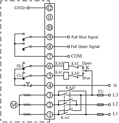
H - 3 phase 380VAC motor with 2 end-position switches

  • Control actuator to open or close by an external inverter to change the phase of supply power.
  • The output terminal of end-position OPEN/CLOSE will send out the event as a passive signal form when the end-position was reached.


Connecting Details:

  1. Connecting a 3 phase AC380V inverter output to P1, P2 and P3, then the actuator can be controlled to open or close the valve by change the 3 phase order.
  2. Connecting AC380V neutral to N(P4).
  3. P5 is used for cooperating with an external switch to control the inverter 3 phase order. This terminal is connected to N(P4) when actuator is not in end-position of CLOSE and disconnected from N(P4) after actuator reached end-position of CLOSE.
  4. P6 is used for cooperating with an external switch to control the inverter 3 phase order. This terminal is connected to N(P4) when actuator is not in end-position of OPEN and disconnected from N(P4) after actuator reached end-position of OPEN.
  5. P7 is the COM for passive contact signal of end-position OPEN/CLOSE which is normally connected to signal GND.
  6. P8 is end-position OPEN terminal which will be connected to COM when actuator reached end-position of open.
  7. P9 is end-position CLOSE terminal which will be connected to COM when actuator reached end-position of close.
  8. Connect earth to P12.

Note:

  • The circuit inside the dashed box is the internal circuit of actuator. While the circuit outside is a demonstration of electrical connection for using actuator.
  • If you have other specific requirements about connecting circuit, please feel free to contact our technical support. 

Choose another actuator with different torque​

50 Nm/20 s

————————–

Optionnel avec

20 Nm/4 S

30 Nm/10 s

50 Nm/60 s

100 Nm/30 s

————————–

Optionnel avec

50 Nm/15 s

100 Nm/60 s


200 Nm/30 s

————————–

Optionnel avec

100 Nm/15 s

200 Nm/60 s


400 Nm/30 s

————————–

Optionnel avec

200 Nm/15 s

400 Nm/60 s


Demande de devis

Cliquez sur « Envoyer » maintenant, nous vous confirmerons ultérieurement le numéro de modèle du produit et le distributeur local, puis nous vous enverrons le devis.

WhatsApp

Scannez le code QR pour discuter dès maintenant avec notre ingénieur...

Demande de devis

Cliquez sur « Envoyer » maintenant, nous vous confirmerons ultérieurement le numéro de modèle du produit et le distributeur local, puis nous vous enverrons le devis.

WhatsApp

Scannez le code QR pour discuter dès maintenant avec notre ingénieur...

Demande de devis

Cliquez sur « Envoyer » maintenant, nous vous confirmerons ultérieurement le numéro de modèle du produit et le distributeur local, puis nous vous enverrons le devis.

WhatsApp

Scannez le code QR pour discuter dès maintenant avec notre ingénieur...

🤝 Construisons ensemble votre marque

✅ ODM

  • Votre logo et votre emballage
  • Formats de sortie personnalisés (4-20 mA, RS485 Modbus, HART, etc.)
  • changements de couleur ou d'étiquette du boîtier
  • Versions compatibles avec le cloud (en option)

✅ OEM

  • Respectez scrupuleusement votre conception et vos spécifications.
  • Confidentialité totale et protection de la propriété intellectuelle
  • Production de haute qualité à prix compétitif
  • Production en petits lots ou à grande échelle
  • 🏭 Recherche et développement et fabrication internesDe la carte de circuit imprimé au boîtier, tout sous un même toit.
  • 💬 Assistance multilingueIngénieurs et commerciaux anglophones.

  • ⚙️ MOQ flexible: Un soutien aux startups comme aux marques internationales.

  • 🚀 Prototypage rapideLivraison de l'échantillon sous 7 à 10 jours.

 Contactez-nous dès aujourd'hui pour demander un catalogue de produits ou obtenir une consultation gratuite.

Demande de devis

Envoyer une demande

WhatsApp

Scannez le code QR pour discuter dès maintenant avec notre ingénieur...

Contactez-nous

Téléphone

(+86) 130 2633 1611

WhatsApp

Ken Bryan

即时客服图标 | Icône de message en direct

Chat sur le site

Cliquez sur l'icône en bas à droite pour discuter avec nous...