工业过程控制系统用普通型及智能型电动执行机构 JB/T 8219—2016

Table of Contents

  • Preface

  • 1 Scope

  • 2 Normative References

  • 3 Terms and Definitions

  • 4 Product Classification and Basic Parameters

    • 4.1 Product Classification

    • 4.2 Basic Parameters

  • 5 Basic Functions of Intelligent Actuators

    • 5.1 Display Function

    • 5.2 Parameter Setting Function

    • 5.3 On-Site Configuration Function

    • 5.4 Fault Self-Diagnosis and Alarm Function

    • 5.5 Communication Function

    • 5.6 Other Functions

  • 6 Requirements

    • 6.1 Basic Performance Requirements

    • 6.2 Performance Requirements Affected by Influencing Factors

    • 6.3 Appearance

    • 6.4 Protection Level of the Enclosure

    • 6.5 Explosion-Proof Performance

  • 7 Test Methods

    • 7.1 Test Conditions

    • 7.2 General Test Provisions

    • 7.3 Basic Error

    • 7.4 Basic Deviation of Position Output Signal

    • 7.5 Hysteresis

    • 7.6 Dead Zone

    • 7.7 Time Delay

    • 7.8 Rated Stroke Time Error

    • 7.9 Start-up Characteristics

    • 7.10 Repeatability Error of Stroke Control Mechanism

    • 7.11 Insulation Resistance

    • 7.12 Insulation Strength

    • 7.13 Temperature Rise

    • 7.14 Long-term Stability

    • 7.15 Maximum and Minimum Control Torque and Thrust Repeatability Error

    • 7.16 Manual-Electric Switching Mechanism

    • 7.17 Basic Functions of Intelligent Actuators

    • 7.18 Noise

    • 7.19 Stepless (Frequency) Speed Regulation

    • 7.20 Influence of Environmental Temperature

    • 7.21 Humidity and Heat Influence

    • 7.22 Influence of Power Supply Voltage

    • 7.23 Influence of Mechanical Vibration

    • 7.24 Influence of Transport Environment

    • 7.25 Electromagnetic Interference Immunity to Radio Frequency Fields

    • 7.26 Electromagnetic Immunity to Electrical Fast Transient Pulses

    • 7.27 Surge (Impact) Immunity

    • 7.28 Electrostatic Discharge Immunity

    • 7.29 Power Frequency Magnetic Field Immunity

    • 7.30 Appearance

    • 7.31 Protection Level of the Enclosure

    • 7.32 Explosion-Proof Performance

  • 8 Inspection Rules

    • 8.1 Factory Inspection

    • 8.2 Type Test

  • 9 Marking, Packaging, and Storage

    • 9.1 Marking

    • 9.2 Packaging

    • 9.3 Storage

Table 1 Basic Performance Technical Indicators
Table 2 Technical Indicators Affected by Influencing Factors
Table 3 Inspection Items

Preface

This standard was drafted according to the rules given in GB/T1.1—2009.
This standard replaces JB/T 8219—1999 “Electric Actuators for Industrial Process Measurement and Control Systems”. The main technical changes compared to JB/T 8219—1999 are as follows:

  • The title of the standard has been changed;

  • The normative references have been updated (see Chapter 2);

  • In the product classification, the original classification based on the relationship between actuator input and output is changed to classification by control method, dividing it into switch-type actuators and regulating-type actuators (see 4.1.2); a method based on the motor drive mode has been added (see 4.1.4); the “damping characteristics, gap, and dead zone” indicators in the 1999 version have been removed (see 4.2 of the 1999 version);

  • The “proportional actuator input signal” from the original standard is modified to the preferred input signal for regulating-type actuators and switch-type actuators (see 4.2.5);

  • Basic functions of intelligent actuators have been added (see Chapter 5);

  • The accuracy grades have been changed from the original “Level 1, 2.5, 5” to “Level 0.5, 1.0, 1.5, 2.5” (see Table 1); the terms “proportional electric actuators” and “integral electric actuators” in the original Table 1 have been modified to “regulating-type actuators” and “switch-type actuators”;

  • The requirements now include “maximum and minimum control torque and thrust repeatability errors”, “basic functions of intelligent actuators”, “RF electromagnetic field radiation immunity”, “electrical fast transient pulse group immunity”, “surge (impact) immunity”, “electrostatic discharge immunity”, and “power frequency magnetic field immunity” (see 6.1.13, 6.1.15, 6.2.6, 6.2.7, 6.2.8, 6.2.9, 6.2.10);

  • Some test methods have been modified or added, such as temperature rise (see 7.13), environmental temperature effects (see 7.20), power supply voltage effects (see 7.22), etc.
    This standard is proposed by the China Machinery Industry Federation and is under the jurisdiction of the National Technical Committee for Industrial Process Measurement and Control and Automation Standardization (SAC/TC124).

General and Intelligent Electric Actuators for Industrial Process Control Systems

1 Scope

This standard specifies the product classification, requirements, test methods, inspection rules, marking, packaging, and storage for ordinary and intelligent electric actuators used in industrial process control systems (hereinafter referred to as actuators).
This standard is applicable to all types of actuators powered by motors, including angular stroke, linear stroke, and multi-turn actuators.

2 Normative References

The following documents are essential for the application of this document. The dated references are applicable to this document only in the versions specified. For undated references, the latest version (including all amendments) is applicable.

  • GB 3836.1 Explosive Atmospheres Part 1: Equipment General Requirements

  • GB 3836.2 Explosive Atmospheres Part 2: Equipment Protected by Flameproof Enclosures “d”

  • GB 4208-2008 Enclosure Protection Rating (IP Code)

  • GB/T 13384 General Technical Conditions for Packaging of Electromechanical Products

  • GB/T 17626.2 Electromagnetic Compatibility Test and Measurement Techniques Electrostatic Discharge Immunity Test

  • GB/T 17626.3 Electromagnetic Compatibility Test and Measurement Techniques Radiated RF Electromagnetic Field Immunity Test

  • GB/T 17626.4 Electromagnetic Compatibility Test and Measurement Techniques Electrical Fast Transient/Burst Immunity Test

  • GB/T 17626.5 Electromagnetic Compatibility Test and Measurement Techniques Surge (Shock) Immunity Test

  • GB/T 17626.8 Electromagnetic Compatibility Test and Measurement Techniques Power Frequency Magnetic Field Immunity Test

  • GB/T 18271.1—2000 General Methods and Procedures for the Performance Evaluation of Process Measurement and Control Devices Part 1: General Principles

  • GB/T 25480 Basic Environmental Conditions and Test Methods for Transport and Storage of Instruments and Meters

  • GB/T 26815—2011 Industrial Automation Instrumentation Terminology Actuator Terminology

3 Terms and Definitions

The terms and definitions in GB/T 26815—2011, as well as those below, apply to this document.

  • Maximum Control Torque: The maximum torque that the actuator can control during operation.

  • Minimum Control Torque: The minimum torque that the actuator can control during operation.

  • Maximum Control Thrust: The maximum thrust that the actuator can control during operation.

  • Minimum Control Thrust: The minimum thrust that the actuator can control during operation.

4 Product Classification and Basic Parameters

4.1 Product Classification

4.1.1 Classification by Output Displacement Type
Actuators are classified based on the type of output displacement as:

  • Angular stroke

  • Linear stroke

  • Multi-turn

4.1.2 Classification by Control Method
Actuators are classified by control method as:

  • Switch-type

  • Regulating-type

4.1.3 Classification by Working Environment
Actuators are classified based on working environment as:

  • Conventional type

  • Explosion-proof type
    (Note: Other types can be used based on requirements.)

4.1.4 Classification by Motor Drive Mode
Actuators are classified by motor drive mode as:

  • Mechanical contact type

  • Electronic non-contact type

4.2 Basic Parameters

4.2.1 Working Environmental Conditions
Actuators should be able to operate under the following conditions:

  • Ambient temperature: -10°C ~ 55°C, or -20°C ~ 60°C, or -30°C ~ 70°C

  • Relative humidity: not exceeding 95%

  • Atmospheric pressure: 86 kPa ~ 106 kPa
    (Note: For actuators used in special environments, the working conditions should be determined through consultation between the user and the manufacturer.)

4.2.2 Power Supply Conditions
Actuators use the following power supplies for operation:

  • AC: Single-phase (220±22)V; Three-phase (380±38)V; Frequency (50±0.5)Hz; Harmonic content less than 5%.

  • DC: (24±2.4)V; (48±4.8)V; Ripple peak value less than 5% of the supply voltage.
    (Note: For special power supply conditions, the user and manufacturer should consult.)

4.2.3 Rated Load
The rated load for actuators is preferably chosen from the following series:

  • Angular stroke [unit: Newton-meters (N·m)]: 6, 16, 40, 100, 250, 600, 1000, 1600, 2500, 4000, 6000, 10000, 16000, …

  • Linear stroke [unit: Newtons (N)]: 250, 400, 600, 1000, 1600, 2500, 4000, 6000, 10000, 16000, 25000, 40000, 60000, …

  • Multi-turn [unit: Newton-meters (N·m)]: 16, 40, 100, 160, 250, 400, 600, 1000, 1600, 2500, …
    (Note: Manufacturers may select other series based on actual conditions.)

4.2.4 Rated Stroke
The rated stroke value for actuators is preferably chosen from the following series:

  • Angular stroke [unit: degrees (°)]: 50, 70, 90, 120, 270, …

  • Linear stroke [unit: millimeters (mm)]: 10, 16, 25, 40, 60, 100, 160, 250, 400, 600, 1000, …

  • Multi-turn [unit: turns (r)]: 5, 7, 10, 15, 20, 40, 80, 120, …
    (Note: Manufacturers may select other series based on actual conditions.)

4.2.5 Input Signal
4.2.5.1 Regulating-type actuators should preferably use the following input signal:

  • DC 4 mA ~ 20 mA
    (Note: Other input signals may be selected according to user requirements.)

4.2.5.2 Switch-type actuators should preferably use the following input signals:

  • Passive contact, DC 24V, AC 220V
    (Note: Other input signals may be selected according to user requirements.)

4.2.6 Switching Frequency
The actuator works under an intermittent reversible duty cycle. When the duty cycle is between 20% and 80%, the number of switches per hour is chosen from the following series: 100, 320, 630, 1200, 1800.
Note 1: The duty cycle refers to the ratio of the actuator’s motor power-on time to the motor power-off cycle time, expressed as a percentage.
Note 2: The duty cycle, switching frequency, and switching time per hour can be specified differently based on user requirements.

5 Basic Functions of Intelligent Actuators

5.1 Display Function
Intelligent actuators can display operational parameters, running status information, signal queries, fault alarms, etc., through a human-machine interface, in Chinese (or other languages according to user requirements).

5.2 Parameter Setting Function
Intelligent actuators can set working parameters such as stroke and torque through the human-machine interface. They can also calibrate 4mA-20mA current output signals.

5.3 On-site Configuration Function
Intelligent actuators must have at least the following on-site configuration functions:

  • On-site setting of the switch contact mode for outputting operational status

  • On-site setting of control modes for both remote and local control

5.4 Fault Self-Diagnosis and Alarm Function
Intelligent actuators can self-diagnose abnormal conditions that occur during operation (e.g., motor overheating, power phase loss, valve jamming) and automatically display fault information locally and output alarms remotely.

5.5 Communication Function
Intelligent actuators can be equipped with optional digital communication interfaces for fieldbus communication control. The fieldbus protocol used should be tested by a relevant authoritative testing agency to confirm whether it complies with the corresponding fieldbus standards.

5.6 Other Functions
Intelligent actuators may also have the following functions:

  • At least 4 switch contact outputs (with no less than 2 switch contacts that retain their status after power loss)

  • Power phase sequence self-adaptation function

  • Position sensors should preferably be non-contact absolute encoders that do not require battery support

  • Torque sensors can continuously measure the actuator’s output torque (thrust)

  • For high-precision control or cases requiring multi-stage speed control, actuators with stepless (frequency) speed control functions should be preferred

6 Requirements

6.1 Basic Performance Requirements
The basic performance of the actuators should meet the specifications in Table 1.

Table 1: Technical Specifications for Basic Performance

Clause No.ItemUnitRegulating ActuatorsSwitch ActuatorsRemarks
   0.5 Grade1.0 Grade1.5 Grade
6.1.1Basic Error%≤ ±0.5≤ ±1.0≤ ±1.5
6.1.2Position Output Signal Error%≤ 0.5≤ 1.0≤ 1.5
6.1.3Hysteresis%≤ 0.5≤ 1.0≤ 1.5
6.1.4Dead Zone (percentage of input range)%≤ 0.5≤ 1.0≤ 1.5
6.1.5Time Delays≤ 1  
6.1.6Rated Stroke Time Error%Not exceeding ±20  
6.1.7Start Characteristics Normal start when the power voltage drops to the negative limit value  
6.1.8Stroke Control Repetition Error Multi-turn: ≤ ±5°Angular Stroke: ≤ ±1°Linear Stroke: ≤ ±1%
6.1.9Insulation Resistance   
6.1.9.1Between input terminals and housing≥20≥50  
6.1.9.2Between input terminals and power terminals≥50≥50  
6.1.9.3Between power terminals and housing≥50≥50  
6.1.10Insulation Strength Test voltage and frequencyTest voltage and frequencyTest voltage for electronically controlled, non-contact driven actuators according to the manufacturer’s requirements
6.1.10.1Between input terminals and housing500 V, 50 Hz1500V, 50 Hz  
6.1.10.2Between input terminals and power terminals1500 V, 50 Hz1500 V, 50 Hz  
6.1.10.3Between power terminals and housing(No breakdown or arc during testing)Nominal voltage < 60V: 500 V, 50 HzNominal voltage 60V~<130V: 1000V, 50 HzNominal voltage 130V~<250V: 1500 V, 50 Hz
6.1.11Temperature Rise°C≤ 60≤ 60 
6.1.12Long-Term Running Stability (after 48 hours of operation) Basic error should still meet 6.1.1Position output signal deviation should still meet 6.1.2Hysteresis should still meet 6.1.3
6.1.13Maximum and Minimum Control Torque and Thrust Repetition Error%≤ ±10  
6.1.14Manual-Electric Switching Mechanism Manual-electric switching should be easy and reliable; handwheel should not rotate during electric operation.  
6.1.15Basic Functions of Intelligent Type (only applicable to intelligent actuators)    
a) Display FunctionNormal    
b) Parameter Setting FunctionNormal    
c) On-Site Configuration Function     
1) Switch Contact Mode for Outputting Running StatusNormal    
2) Remote and Local Switch Control FunctionNormal    
d) Fault Self-Diagnosis and Alarm Function:     
1) Motor Overheating AlarmNormal    
2) Power Phase Loss AlarmNormal    
e) Power Phase Sequence Self-Adaptive FunctionNormal    
f) Output Torque (Thrust) Continuous Measurement FunctionNormal    
6.1.16Noise (No Load) ≤75 dB(A)  
6.1.17Stepless (Variable Frequency) Speed Regulation No load actuator speed can continuously decrease from the rated speed to nearly zero; with 85% rated load, actuator speed can at least drop to one-tenth of the rated speed, with speed error not exceeding ±10%.Only applicable to stepless variable frequency speed actuators. 

6.2 Performance Requirements Affected by Environmental Factors
Under the influence of environmental factors, the performance of actuators should still meet the specifications in Table 2.

Table 2: Technical Specifications for Environmental Factors’ Impact

Clause No.ItemUnitRegulating ActuatorsSwitch Actuators
6.2.1Temperature Effect (for every 10°C change):   
— Output Low End Value Change%≤ 0.75≤ 1.0≤ 1.5
— Output High End Value Change%≤ 0.75≤ 1.0≤ 1.5
6.2.2Humid Heat Impact (Temperature 40°C ± 2°C and Humidity 91%~95%, After 48h Test Insulation Resistance)  
— Between Input Terminals and Housing≥2≥2  
— Between Input Terminals and Power Terminals≥2≥2  
— Between Power Terminals and Housing≥2≥2  
6.2.3Power Voltage Impact (When the power voltage changes to the positive and negative limits from nominal value):%  
— Output Low End Value Change%≤ 0.75≤ 1.0≤ 1.5
— Output High End Value Change%≤ 0.75≤ 1.0≤ 1.5
6.2.4Mechanical Vibration Impact:   
— Vibration Frequency: 10Hz~150Hz%≤ 1≤ 1.5≤ 2.5
— Displacement Amplitude: 0.15 mmAfter the test: No loosening of fasteners, no mechanical damage  
— Acceleration Amplitude: 20 m/s²After the test: No loosening of fasteners, no mechanical damage  
6.2.5Transport Environment Impact:   
— Temperature: High Temperature: 55°CLow Temperature: -40°C 
— ShockAcceleration: 100m/s² ±10m/s²Pulse Repetition Frequency: 60 times/min~100 times/minShock Times: 1000 ±100 timesFree Fall Height: 100mm
6.2.6Radio Frequency Electromagnetic Field Immunity   
— Frequency: 80 MHz~1000 MHz, Distance: 3m, Field Strength: 3 V/m, AM 1 kHz, 80% modulation%≤0.5≤1.0≤1.5

6.3 Appearance

The metal surface coating or plating of the actuator should be smooth, intact, and free from peeling, scratches, or blemishes. Fasteners should be secure, and movable parts should be flexible and reliable. Actuators with display functions should have a clear, undamaged display screen, with no liquid leakage, missing characters, or garbled text.

6.4 Protection Grade of Enclosure

The protection grade of the intelligent actuator’s enclosure should be no less than IP67 as per GB4208-2008, and for regular actuators, it should be no less than IP65.

6.5 Explosion-Proof Performance

The explosion-proof actuator’s type, level, and temperature group should meet the requirements of GB 3836.1 and GB 3836.2. Its production and certification must follow the national regulations.

7 Test Methods

7. Test Methods

7.1 Test Conditions

7.1.1 Environmental Conditions

7.1.1.1 Reference Atmospheric Conditions

The reference performance of the actuator should be tested under the following atmospheric conditions:

  • Ambient temperature: 20°C ± 2°C;

  • Relative humidity: 60% to 70%;

  • Atmospheric pressure: 86 kPa to 106 kPa.

7.1.1.2 General Atmospheric Conditions

When tests are not conducted under reference atmospheric conditions, it is recommended to perform tests under the following atmospheric conditions:

  • Ambient temperature: 15°C to 35°C;

  • Relative humidity: 45% to 75%;

  • Atmospheric pressure: 86 kPa to 106 kPa.

7.1.1.3 Other Environmental Conditions

Except for the Earth’s magnetic field, other external magnetic fields and mechanical vibrations should be negligible.

7.1.2 Power Conditions

7.1.2.1 Nominal Values

As specified in 4.2.2.

7.1.2.2 Tolerances

The tolerances for the test conditions are as follows:

  • Rated voltage: ±1%;

  • Rated frequency: ±1%;

  • Harmonic content: less than 5%.

7.2 General Test Regulations

7.2.1 The tested product should be in its normal installation position. The power supply can be connected and preheated for 1 hour to allow the internal temperature of the tested product to stabilize.

7.2.2 The zero position of the tested product can be adjusted before the test. Unless otherwise specified, no adjustment should be made during the test.

7.2.3 Unless otherwise specified, the tested product and related testing equipment should be stabilized under reference working conditions before measurements are taken, and all work conditions that may affect the measurement results should be observed and recorded.

7.2.4 The accuracy of standard instruments used in the tests should be stated in the test report, and the basic error limit should be less than or equal to one-third of the basic error limit of the tested product. The range of the instrument should match the range of the measured values.

7.2.5 During the test, the current input signal should be increased or decreased slowly, approaching the test points in the same direction, ensuring no overshoot. The increasing signal should be considered as the positive stroke, and the decreasing signal as the reverse stroke.

7.2.6 Unless otherwise specified, the output shaft (rod) of the actuator should be loaded with the rated load during the test. The load is considered positive when its action direction coincides with the direction of motion of the output shaft (rod); otherwise, it is considered negative.

7.2.7 Unless otherwise specified, test measurement points should be at 0%, 25%, 50%, 75%, and 100% of the input range. Each test point should be measured three times in both the increasing and decreasing signal directions. Factory inspection allows for measuring each test point once.

7.2.8 Unless otherwise specified, the influencing factors for the test should only change within the specified working conditions. All other working conditions should remain constant under reference conditions.

7.2.9 If it is not possible to conduct influence factor tests under reference atmospheric conditions due to conditions, the test can be performed under general atmospheric conditions.

7.2.10 Unless otherwise specified, the rated stroke range for the test is as follows:

  • Multi-turn: 10 turns;

  • Angle stroke: 90°;

  • Linear stroke: 16 mm.

7.3 Basic Error

The basic error is calculated by slowly increasing or decreasing the input signal, recording the input signal values and the stroke values of the output shaft (rod) in both positive and reverse stroke directions, according to Formula (1).
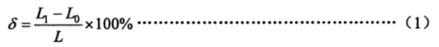
Formula (1)

Where:

  • δ: Basic error, %;

  • L1: Stroke value of the output shaft (rod), in degrees (°), millimeters (mm), or turns (r);

  • Lo: Theoretical stroke value of the output shaft (rod), in degrees (°), millimeters (mm), or turns (r);

  • L: Rated stroke range of the output shaft (rod), in degrees (°), millimeters (mm), or turns (r).

Check if the basic error at each measurement point exceeds the limit specified in 6.1.1.

7.4 Position Output Signal Basic Deviation

The position output signal is connected to a 250Ω load impedance, and the actuator is run to the “fully closed” position. Adjust the position output signal to 4 mA; run the actuator to the “fully open” position, and adjust the position output signal to 20 mA. Then, run the actuator and record the position output signal values at each point in both the positive and reverse stroke directions. Basic deviation is calculated according to Formula (2).
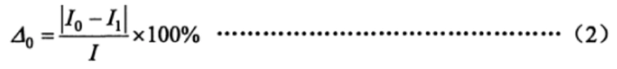
Formula (2)

Where:

  • △0: Position output signal basic deviation, %;

  • Io: Theoretical value of the position output signal, in milliamps (mA);

  • I1: Measured value of the position output signal, in milliamps (mA);

  • I: Range of the position output signal, in milliamps (mA). (For 4 mA to 20 mA, I = 16 mA; for 0 mA to 20 mA, I = 20 mA).

Check if the basic deviation at each measurement point exceeds the limit specified in 6.1.2.

7.5 Hysteresis

The hysteresis of the actuator is determined by the maximum algebraic difference between the basic errors of the forward and reverse strokes measured at each test point, as determined in 7.3 and 7.4.

7.6 Dead Zone

For regulating actuators, the dead zone should be measured at 25%, 50%, and 75% of the rated stroke. The measurement steps are as follows:

  • Slowly increase (or decrease) the input signal until a perceptible stroke change occurs at the output shaft (rod) and record the input signal value at this point I (mA);

  • Then slowly decrease (or increase) the input signal in the opposite direction until a perceptible stroke change occurs at the output shaft (rod) and record the input signal value I² (mA).

The dead zone is calculated according to Formula (3).
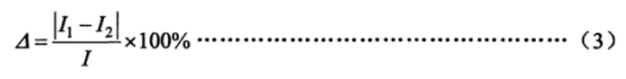
Formula (3)

Where:

  • △: Dead zone, %.

7.7 Time Delay

Apply a step signal of 15% of the input range to the input signal terminal of the regulating actuator, use an oscilloscope to record the input signal curve and position output signal curve, and observe the time difference from the initial input signal to the start of the output signal change to see if it exceeds the limit specified in 6.1.5.

7.8 Rated Stroke Time Error

Apply 45% to 55% of the rated load on the actuator, apply a step signal sufficient to move the actuator’s output shaft (rod) through the rated stroke, and record the time for the output shaft (rod) to move the rated stroke. The rated stroke time error is calculated according to Formula (4).

Formula (4)

Where:

  • δt: Rated stroke time error, %;

  • t1: Measured time for the output shaft (rod) to move the rated stroke, in seconds (s);

  • t: Theoretical rated stroke time, in seconds (s).

7.9 Start Characteristics

Apply a reverse rated load on the output shaft (rod) of the actuator, and change the power supply voltage to the lower limit value. Then apply the input signal and observe whether the actuator can start normally.

7.10 Stroke Control Mechanism Repeatability Error

For actuators with a stroke control mechanism, apply 25% to 30% of the rated load to the output shaft (rod) and operate the actuator alternately in the forward and reverse strokes five times. Observe and record the stroke values of the output shaft (rod) when the stroke control mechanism switches. Calculate the error of each recorded value compared to the base value and determine whether the error exceeds the limit specified in 6.1.8.

7.11 Insulation Resistance

Under general atmospheric conditions and with the actuator unloaded, disconnect the power supply to the tested product and keep the power switch in the “on” position. Short-circuit the input and power terminals, then use a 500V DC insulation resistance tester to measure the insulation resistance between the terminals as specified in 6.1.9.

7.12 Insulation Strength

Under general atmospheric conditions and with the actuator unloaded, disconnect the power supply and keep the power switch in the “on” position. Short-circuit the input and power terminals, then according to the voltage and frequency specified in 6.1.10, slowly raise the test voltage from zero to the specified value and hold for 1 minute. Observe if there is any breakdown or arcing, then slowly lower the test voltage to zero and disconnect the test power.

7.13 Temperature Rise

Before the test, measure the cold resistance of the motor and power transformer windings using a bridge, then continuously run for 12 hours as per 7.14 and immediately measure the hot resistance of the motor and power transformer windings. Calculate the temperature rise according to Formula (5).

Formula (5)

Where:

  • Q: Temperature rise, in Celsius (°C);

  • R₂: Hot resistance of the winding, in ohms (Ω);

  • R₁: Cold resistance of the winding, in ohms (Ω);

  • T1: Room temperature during cold resistance measurement, in Celsius (°C);

  • T₂: Room temperature during hot resistance

7.14 Long-Term Operation Stability

Operate the actuator within its rated stroke and apply 30% of the rated load, with a duty cycle of 20% to 80%. Perform 48 hours of operation as required in 4.2.6, with the number of cycles per hour. After the test, verify if the actuator meets the requirements of 6.1.12.

7.15 Maximum and Minimum Control Torque and Thrust Reproducibility Error

Test procedure as follows: a) Install the actuator on the test bench, set the torque protection value in both the open and close directions to the maximum control torque or thrust value, and gradually load the actuator until a “torque overload” or “thrust overload” alarm is triggered. Measure the output torque or thrust value. Measure three times in each direction and take the average value as the base value of output torque or thrust. b) Install the actuator on the test bench, set the torque protection value in both open and close directions to the minimum control torque or thrust value, and gradually load the actuator until a “torque overload” or “thrust overload” alarm is triggered. Measure the output torque or thrust value. Measure three times in each direction and take the average value as the base value of output torque or thrust. c) Calculate the reproducibility error of the control torque or thrust according to formula (6).
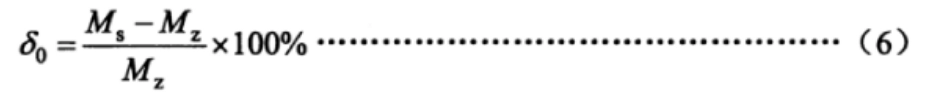
Formula 6:

In this formula:

  • δ0: Reproducibility error of control torque or thrust, in %

  • Ms: Measured output torque or thrust value, in N·m (or thrust in N)

  • Mz: Base value of output torque or thrust, in N·m (or thrust in N).

7.16 Manual-Electric Switch Mechanism

Test procedure as follows: a) No-load switch check. Switch the actuator from electric to manual mode, rotate the handwheel to turn the output shaft clockwise and counterclockwise for at least one full rotation; then, operate the actuator electrically to turn the output shaft in both directions for at least one full rotation. Repeat twice and confirm if it meets the requirements of 6.1.14. b) Loaded switch check. Install the actuator on the test bench, adjust the protection torque in both open and close directions to the maximum control torque, and gradually load the actuator until the torque switch activates. After stopping, without unloading, repeat the test in part a) to confirm if it meets the requirements of 6.1.14.

7.17 Intelligent Features

7.17.1 Display Function

Check whether the working parameters, operation status information, fault alarms, and other display information are normal, and whether the display content is complete and clear through the human-machine interface.

7.17.2 Parameter Setting Function

Without opening the electrical cover, check whether the human-machine interface allows for setting parameters such as stroke, torque, current input signal calibration, and output signal adjustment.

7.17.3 On-Site Configuration Function

Without opening the electrical cover, use the human-machine interface to set the actuator’s 4-way switch contact outputs as follows: open-position closed, open-position open, closed-position closed, closed-position open. Start the actuator to the open and closed positions, checking whether the switch contact outputs meet the set requirements.

If applicable, check the behavior after power failure and adjust parameters such as torque protection.

7.17.4 Fault Self-Diagnosis and Alarm Function

In no-load conditions, apply power to the actuator and disconnect the motor temperature lead from the actuator’s control system to check if the motor overheat alarm is triggered.

7.17.5 Power Sequence Self-Adaptive Function

For actuators using three-phase power, change the phase sequence of the power supply and confirm whether the switching direction is correct in both local and remote control modes.

7.17.6 Continuous Output Torque (Thrust) Measurement Function

Place the actuator on the test bench, and during operation, change the applied torque (thrust) continuously to observe if the displayed torque (thrust) values change accordingly on the human-machine interface.

7.18 Noise

In a room with the windows and doors closed and background noise not exceeding 45 dB, perform a no-load startup of the actuator and measure the noise at a distance of 1 meter from the actuator surface. Confirm that the noise meets the requirements in 6.1.16.

7.19 Stepless (Frequency Conversion) Speed Regulation

Set the actuator to reduce speed when it reaches the target position, and test whether the speed changes within the specified range at different load conditions to confirm its compliance.

7.20 Environmental Temperature Impact

Under no-load conditions, the actuator should be placed into a temperature test chamber. The test temperatures and test sequence are as follows:

  • For actuators with a working ambient temperature of -10°C to 55°C:

    • 20°C (reference), 40°C, 55°C, 20°C, 0°C, -10°C, 20°C;

  • For actuators with a working ambient temperature of -20°C to 60°C:

    • 20°C (reference), 40°C, 60°C, 20°C, 0°C, -20°C, 20°C;

  • For actuators with a working ambient temperature of -30°C to 70°C:

    • 20°C (reference), 45°C, 70°C, 20°C, 0°C, -30°C, 20°C.

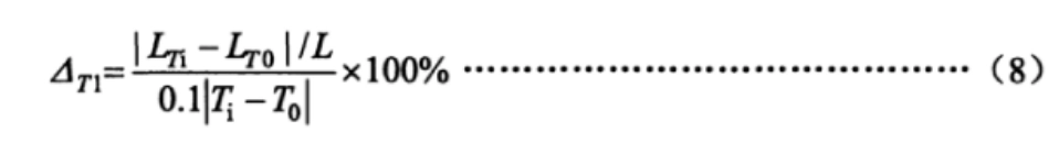
If agreed upon by all parties, tests may be conducted at just four temperature points: 20°C (reference), the maximum temperature, the minimum temperature, and 20°C. The permissible tolerance at each temperature point is ±2°C. At each temperature point, the temperature should be maintained for 2 hours to allow the product’s internal components to reach thermal stability. At the full stroke’s 0% and 100% positions, the low-end and high-end values of the proportional control and position signal output should be measured. The average of three measurements at each temperature point should be taken. The changes in the low-end and high-end values at each temperature point, when the temperature changes by 10°C, should be calculated using formulas (7) and (8), and it should be confirmed that the results meet the requirements of section 6.2.1.
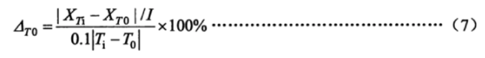
Where:

  • △T0: The change in the low and high-end values of the position output signal when the temperature changes by 10°C, in %;

  • XTi: The measured low and high-end values of the position output signal at the adjacent temperature, in milliamps (mA);

  • XT0: The measured low and high-end values of the position output signal at the starting temperature, in milliamps (mA);

  • Ti: The adjacent temperature, in degrees Celsius (°C);

  • T0: The starting temperature, in degrees Celsius (°C);

  • △T1: The change in the low and high-end values of the output shaft (rod) when the temperature changes by 10°C, in %;

  • LTi: The measured low and high-end stroke values of the output shaft (rod) at the adjacent temperature, in degrees (°), millimeters (mm), or rotations (r);

  • LT0: The measured low and high-end stroke values of the output shaft (rod) at the starting temperature, in degrees (°), millimeters (mm), or rotations (r).

7.21 Humidity Impact

Place the actuator in a temperature and humidity chamber, raise the temperature to 40°C ± 2°C, and adjust the humidity to 91%–95%, maintaining it for 48 hours. After the test, check the actuator’s insulation resistance as specified.

7.22 Power Supply Voltage Influence

Under no-load conditions, the power supply voltage of the actuator is adjusted from the nominal value to both the upper and lower limit values. At the 0% and 100% positions of the full stroke, the low-end and high-end values of the proportional control and position signal outputs are measured. The average of three measurements at each point is taken, and the changes in the lower limit and range are calculated using formulas (9) and (10). The results should be verified to meet the requirements of section 6.2.3.
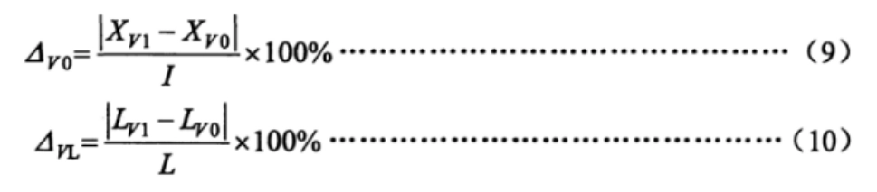
Where:

  • △V0: The change in the low and high-end values of the position output signal when the power supply voltage changes, in %;

  • XV1: The measured low and high-end values of the position output signal at the upper and lower limit voltages, in milliamps (mA);

  • XV0: The measured low and high-end values of the position output signal at the nominal voltage, in milliamps (mA);

  • △VL: The change in the low and high-end values of the output shaft (rod) when the power supply voltage changes, in %;

  • LV1: The measured low and high-end stroke values of the output shaft (rod) at the upper and lower limit voltages, in degrees (°), millimeters (mm), or rotations (r);

  • LV0: The measured low and high-end stroke values of the output shaft (rod) at the nominal voltage, in degrees (°), millimeters (mm), or rotations (r).

7.23 Mechanical Vibration Influence

Under no-load conditions, the actuator is installed on a vibration test stand. The actuator is run to both the 0% and 100% positions of the full stroke. Sweep frequency vibration is applied at a frequency of 10Hz to 150Hz in three mutually perpendicular directions to identify the resonance point. If a resonance point is found, vibration tests are conducted at the resonance frequency for 30 minutes. If no resonance point is found, a 30-minute vibration test is conducted at a frequency of 150Hz.

During the test, the low-end and high-end values of the actuator’s output are measured. The changes in the low-end and high-end values are calculated using formulas (11) and (12). The results should be verified to meet the requirements of section 6.2.4.
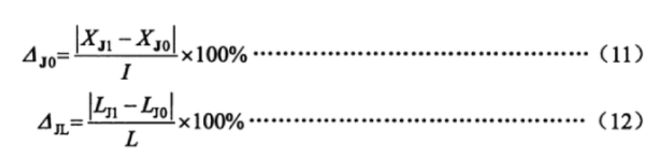
Where:

  • △J0: The change in the low and high-end values of the position output signal due to mechanical vibration, in %;

  • XJ1: The measured low and high-end values of the position output signal during the vibration test, in milliamps (mA);

  • XJ0: The measured low and high-end values of the position output signal before the vibration test, in milliamps (mA);

  • △JL: The change in the low and high-end values of the output shaft (rod) due to mechanical vibration, in %;

  • LJ1: The measured low and high-end stroke values of the output shaft (rod) during the vibration test, in degrees (°), millimeters (mm), or rotations (r);

  • LJ0: The measured low and high-end stroke values of the output shaft (rod) before the vibration test, in degrees (°), millimeters (mm), or rotations (r).

7.24 Transportation Environmental Impact

Temperature, shock, and free-fall tests shall be performed according to the test parameters specified in section 6.2.5 of this standard and the methods in GB/T 25480. After the tests, the zero position can be adjusted, followed by performance testing and visual inspection.

Note: If the environmental temperature influence test has already been performed at 55°C (or higher), the high-temperature test can be waived.

7.25 Radio Frequency Electromagnetic Field Radiation Immunity

Under no-load conditions, the actuator is moved to the 50% position of the full stroke. A radiated electromagnetic field in the frequency range of 80 MHz to 1000 MHz with an intensity of 3V/m is applied at a distance of 3 meters from the actuator, in accordance with the requirements of GB/T 17626.3. During this test, the changes in position feedback output signal or output shaft (rod) stroke values are observed and recorded to confirm that the values meet the requirements of section 6.2.6 of this standard.

7.26 Electrical Fast Transient/Burst Immunity

Under no-load conditions, the actuator is moved to the 50% position of the full stroke. The test voltage is applied according to the requirements of GB/T 17626.4, with a positive and negative 1000V on the power supply terminal and a positive and negative 500V on the signal input terminal. During this test, the changes in position feedback output signal or output shaft (rod) stroke values are observed and recorded to confirm that the values meet the requirements of section 6.2.7 of this standard.

7.27 Surge (Impulse) Immunity

Under no-load conditions, the actuator is moved to the 50% position of the full stroke. A positive and negative 1kV voltage is applied between the actuator’s power supply line and ground, as per GB/T 17626.5. During this test, the changes in position feedback output signal or output shaft (rod) stroke values are observed and recorded to confirm that the values meet the requirements of section 6.2.8 of this standard.

7.28 Electrostatic Discharge Immunity

Under no-load conditions, the actuator is moved to the 50% position of the full stroke. The actuator’s shell is securely grounded. Positive and negative 4kV contact discharge and then positive and negative 8kV air discharge are applied to the actuator, following the requirements of GB/T 17626.2. During this test, the changes in position feedback output signal or output shaft (rod) stroke values are observed and recorded to confirm that the values meet the requirements of section 6.2.9 of this standard.

7.29 Power Frequency Magnetic Field Immunity

Under no-load conditions, the actuator is placed on the external magnetic field test stand and moved to the 50% position of the full stroke. The magnetic field strength is 400 A/m, and the test directions are X/Y/Z, in accordance with GB/T 17626.8. During this test, the changes in position feedback output signal or output shaft (rod) stroke values are observed and recorded to confirm that the values meet the requirements of section 6.2.10 of this standard.

7.30 Appearance

Visual and tactile methods should be used to check whether the surface is flat and smooth, without cracks, burrs, or other defects that affect the appearance. The surface coating should be securely attached, flat, smooth, and uniform in color, with no oil stains, indentations, or other mechanical damage. For actuators with display functions, the display should be clearly visible without missing characters.

7.31 Enclosure Protection Level

The IP67 or IP65 enclosure protection test should be carried out according to the method specified in GB 4208—2008.

7.32 Explosion-Proof Performance

Explosion-proof tests should be conducted by a nationally recognized testing unit, according to the requirements of GB 3836.1 and GB 3836.2.

8 Inspection Rules

8.1 Factory Inspection:

  • Each actuator must be inspected and approved by the manufacturer’s quality inspection department. Only after the inspection department issues a product certificate of conformity can the product be shipped.

  • The factory inspection items are specified in Table 3.

8.2 Type Testing:

  • Type testing should be performed under the following circumstances:

    • The identification of newly developed products.

    • For products in normal production, if there are significant changes in structure, materials, or processes that may affect product performance.

    • If required by relevant national authorities.

  • If the product has been discontinued for over one year.

    • If the product has been in continuous production for more than three years.

  • During type testing, the sampling method should comply with the provisions of GB/T 18271.1—2000, section 6.7.

8.3 Inspection Items: Table 3 lists the specific items for factory inspection and type testing, indicating which items apply to which type of actuator (adjustable or switch type). The inspection items include errors, repeatability errors, insulation resistance, etc.

Inspection Items

No.ItemFactory InspectionType InspectionAdjustment TypeSwitch TypeTechnical RequirementsTest Method
1Basic Error 6.1.17.3
2Position Output Signal Basic Deviation6.1.27.4
3Hysteresis6.1.37.5
4Dead Zone6.1.47.6
5Time Delay6.1.57.7
6Rated Stroke Time Error6.1.67.8
7Starting Characteristics6.1.77.9
8Stroke Control Mechanism Reproducibility Error6.1.87.1
9Insulation Resistance6.1.97.11
10Insulation Strength6.1.107.12
11Temperature Rise 6.1.117.13
12Long-Term Operation Stability6.1.127.14
13Maximum and Minimum Control Torque and Thrust Reproducibility Error6.1.137.15
14Manual-Electric Switching Mechanism6.1.147.16
15Basic Functions of Intelligent Type****6.1.157.17
16Noise 6.1.167.18
17Stepless (Frequency) Speed Regulation6.1.177.19
18Environmental Temperature Impact 6.2.17.2
19Damp Heat Impact  6.2.27.21
20Power Supply Voltage Impact  6.2.37.22
21Mechanical Vibration Impact  6.2.47.23
22Transportation Environmental Impact  6.2.57.24
23Radio Frequency Electromagnetic Field Radiation Immunity ** 6.2.67.25
24Electrical Fast Transient/Burst Immunity ** 6.2.77.26
25Surge (Impact) Immunity ** 6.2.87.27
26Electrostatic Discharge Immunity**6.2.97.28
27Power Frequency Magnetic Field Immunity **6.2.107.29
28Appearance6.37.3
29Enclosure Protection Level6.47.31
30Explosion-Proof Performance 6.57.32

Note:

  • “△” indicates an item that needs to be inspected.

  • “—” indicates an item that does not require inspection.

  • “*” indicates that the item is only applicable to intelligent type actuators.

9 Marking, Packaging, and Storage

9.1 Marking:

  • A nameplate should be affixed to a conspicuous location on the actuator, indicating the following information:

    • Manufacturer’s name and trademark.

    • Product name and model.

    • Main technical parameters of the product.

    • Operating environment temperature.

    • Protection level.

    • Power supply conditions (voltage, current, and frequency).

    • Manufacture date and serial number.

  • For explosion-proof actuators, in addition to the above, the nameplate should also display:

    • The national explosion-proof symbol in the upper right corner.

    • Explosion-proof grade.

    • Explosion-proof certificate number.

9.2 Packaging:

  • Products should be packaged according to the requirements of GB/T 13384. The packaging box should include a product certificate, relevant technical documents, and a packing list.

  • The packing list should include the following information and be stamped with the inspection personnel’s seal:

    • Manufacturer’s name and address.

    • Product name and model.

    • The names and quantities of the attached documents.

    • Product certificate.

    • Quantity of items packed.

    • Packing date.

  • The packaging should be marked with the following details:

    • Manufacturer’s name.

    • Product name and model.

    • Instructions such as “This Side Up,” “Handle with Care,” etc.

    • Gross weight and external dimensions (length × width × height).

9.3 Storage:

  • Products should be stored in a ventilated indoor environment with a temperature range of -10°C to 45°C and relative humidity not exceeding 85%. The storage environment should not contain harmful substances that could cause corrosion to the products.

These regulations ensure the quality and performance of actuators and prevent damage during transportation and storage.